An infinity mirror with an RGB LED strip that can change its color using Infineon’s 3D magnetic sensor knob connected to an Arduino MKR1000.
Things used in this project
Hardware components | ||||||
 |
| × | 1 | |||
 |
| × | 1 | |||
 |
| × | 3 | |||
| × | 1 | ||||
 |
| × | 1 | |||
Software apps and online services | ||||||
 |
| |||||
Hand tools and fabrication machines | ||||||
 |
| |||||
Story
When I saw the infinity mirror effect for the first time, I was impressed with it.
I wanted to build my own version of it, and so, I decided to use Infineon’s 3D magnetic sensor kit with the rotator knob to control colors on an infinity mirror with an RGB LED strip.
Before proceeding to the actual build, make sure to check out this demonstration video of the final product:
Note: The infinity effect is not visible that much; due to the camera and also I need to experiment with the placement of the mirrors to make it more pronounced.
These are the parts needed to build it (only the electronics):
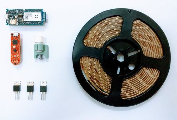
The Details
My inspiration for this project is techydiy’s infinity mirror here. Have a look at it to understand the concept of the infinity mirror.
Because the 3D Magnetic 2Go kit doesn’t have enough PWM pins, I used the Arduino MKR1000 board along with that so that I could easily add anything else to the infinity mirror.
Other than that, the color changing algorithm works by converting the RGB values (from 0 to 255) to HSV (Hue Saturation Value) where changing the value of hue from 0 to 360 will change the color of the LED.
Note: I didn’t write the code for this conversion from HSVtoRGB. After searching online, I found the code from this website here. Therefore, I used the algorithm modified it to work with the 3D Magnetic 2Go kit.
This is the code snippet for the conversion:
void setLedColorHSV(int h, double s, double v) {
 //this is the algorithm to convert from RGB to HSV
 double r=0;
 double g=0;
 double b=0;
 double hf=h/60.0;
 int i=(int)floor(h/60.0);
 double f = h/60.0 - i;
 double pv = v * (1 - s);
 double qv = v * (1 - s*f);
 double tv = v * (1 - s * (1 - f));
 switch (i)
 {
 case 0: //rojo dominante
   r = v;
   g = tv;
   b = pv;
   break;
 case 1: //verde
   r = qv;
   g = v;
   b = pv;
   break;
 case 2:
   r = pv;
   g = v;
   b = tv;
   break;
 case 3: //azul
   r = pv;
   g = qv;
   b = v;
   break;
 case 4:
   r = tv;
   g = pv;
   b = v;
   break;
 case 5: //rojo
   r = v;
   g = pv;
   b = qv;
   break;
 }
 //set each component to a integer value between 0 and 255
 int red=constrain((int)255*r,0,255);
 int green=constrain((int)255*g,0,255);
 int blue=constrain((int)255*b,0,255);
 setLedColor(red,green,blue);
}
Below is a summary of how the whole project works:
- The 3D Magnetic 2Go sends the knob’s current position from 0 to 360 degrees through its hardware serial port.
- The MKR1000 is connected to the 3D Magnetic 2Go’s UART pins, and it parses the angle sent earlier.
- This angle is used in the code snippet showed above in place of hue (which as I said before ranges from 0 to 360).
- This function generates three values (red, green and blue) each ranging from 0 to 255, based on that angle.
- Using analogWrite on these values to the RGB LED strip connected to the MKR1000 (using transistors like TIP120, of course!) allows you to make the light change color to the brightest colors on the color wheel, just by rotating the knob, resulting in a beautiful effect.

That being said, let’s move on to the project itself.
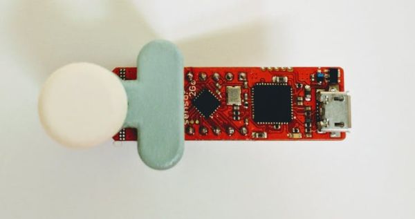
Configuring the 3D Magnetic 2Go Kit
This is the rotator knob attached to the kit:
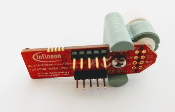
And this is the pin-out of the kit:

Note: I will be using the Arduino IDE to program the kit (version 1.1.2).
Assuming you know the basics like how to upload code and have already set-up the kit to receive sketches from the Arduino IDE, this step will be very easy.
Simply download the attached code for the XMC1100.
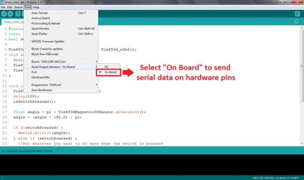
Select the right board and COM port and set “Serial Output Selection” to “PC”. Once done, upload the code and open the serial monitor. You should see a number like this from 0 to 360, which changes by rotating the knob:

If you do, it means everything is okay, upload the same code again, but this time, set “Serial Output Selection” to “On Board”, and make sure it is uploaded properly.
Now you won’t see any output in the Serial Monitor, this is perfectly okay, just move on to the next step.
Configuring the MKR1000
This is the MKR1000:
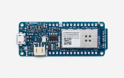
And this is the pin-out of the MKR1000 for your reference:
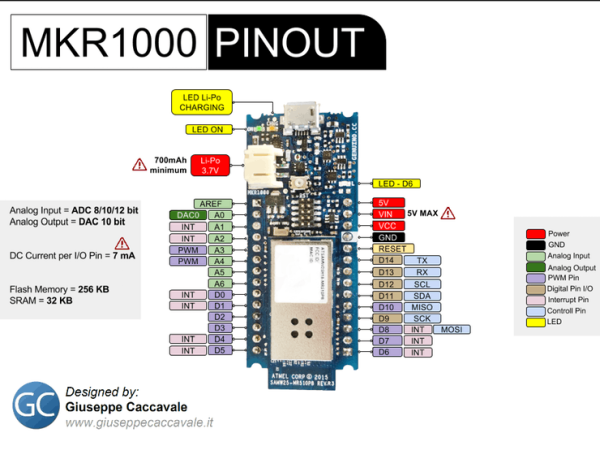
Download the attached code for the Arduino MKR1000 and simply upload it to the Arduino MKR1000. That was easy, wasn’t it?
Connecting Everything and Testing
Now, just connect the Tx pin of one board to the Rx pin of the other, and the Rx pin of one board to the Tx of the other, and connect the 3.3v supply from the MKR1000 to the 3.3v pin on the XMC2Go (if you want!), and make sure the grounds are connected too.
Note: I have connected 3.3v from the MKR1000to the XMC2Go; this will power up the XMC2Go directly from the MKR1000. Quoting from the XMC2Go pin-out diagram:
If board is powered through 3.3v pin, it is not recommended to power through USB and vice versa
This is how they should look:
Note: I would recommend that you first build all of the electronics part, and when it works perfectly, then move on tobuilding the infinity mirror itself.
If you want to test if the connection between the MKR1000 and the 3D magnetic sensor kit is okay, connect the MKR1000 to your computer’s USB port, open the serial monitor at 9600 bauds. You should see this:
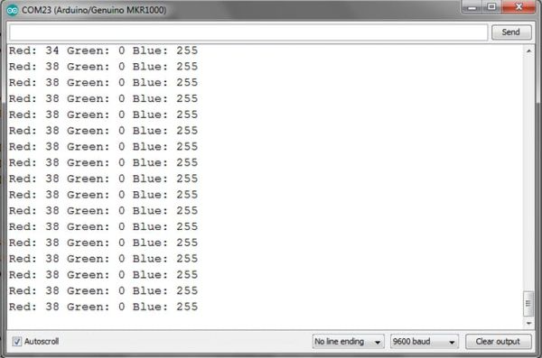 This is the angle from the knob converted to RGB values. Again, rotating the knob will change these.
What is happening is that the 3D Magnetic Sensor kit is sending the angle the knob is on (from 0 to 360 degrees), and the MKR1000 parses that angle and converts it into the RGB color codes (from 0 to 255 each), looping through all colors. Rotate the knob and see the values change.
Now it is time to wire up the transistors to the MKR1000. Use this connection diagram:
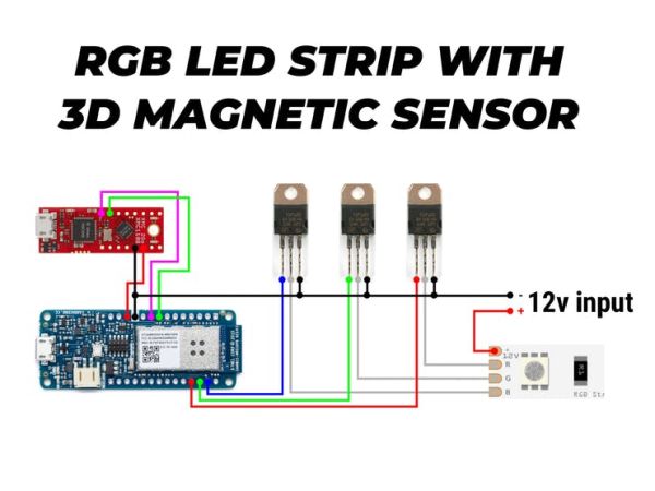
Note: I am using the common anode type RGB LED strip, and this article on Adafruit was very helpful on setting it up.
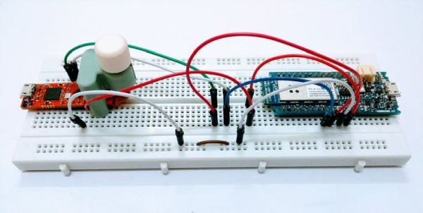
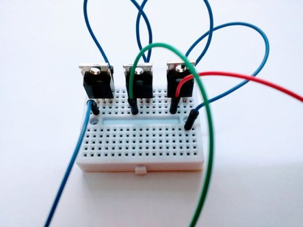
I wired up the transistors on a separate small breadboard:
So after connecting everything up:
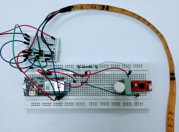
Plug in the 12 volts supply for the LED strip, and the MKR1000’s power (I assume you have powered the XMC2Go from the 3.3v on the MKR1000), and the LED strip should light up like this:
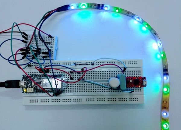
Rotate the knob and see the color change:

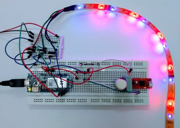
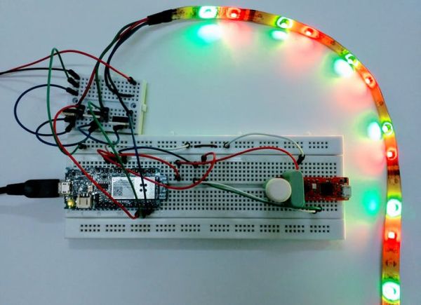
A video of the color changing LED strip with the knob, looping through all the colors:
Making the Infinity Mirror
Now that you are done with the electronics and are able to change the color on the RGB LED strip, we move on to making the infinity mirror itself.
I won’t be going into much detail on this because I’m no expert; it was my first time making something like this, but still the end result wasn’t that bad. Again, I saw this video on YouTube, and it really helped me in building it.
These are a few images of how I built it, just to make you understand the concept.
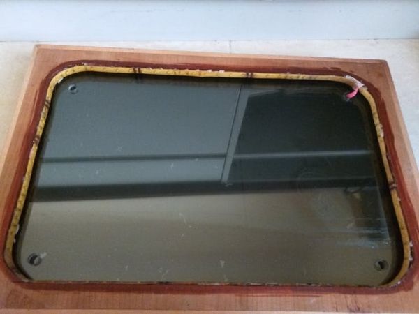
I already had this wooden frame which I used as a frame for exposure when making PCBs, and it appeared to work much better as an infinity mirror:
:
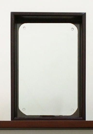

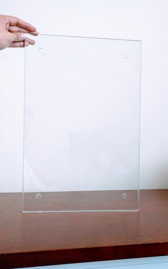
The frame also has this clear glass which can be removed:
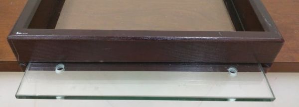
But to get the infinity mirror illusion to work, the glass needs to be tinted. To do that, first the glass needs to be cleaned:
I applied this car window tint (which I got from an auto shop) to the glass using soapy water and a card for pressing out the bubbles.

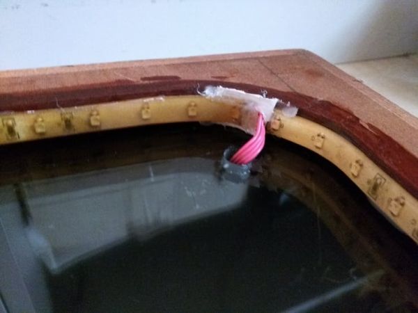
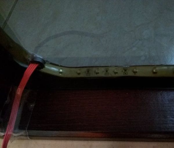
Now for another completely reflective mirror, which goes at the back of the frame, but because I don’t have that at the moment, I just placed the frame (complete with the RGB LED strip attached) in front of a dressing table mirror to check. Finally changing the color of the infinity mirror using the 3D Magnetic Sensor knob:
Final Touches
So now you are able to change the color of an RGB LED strip using the rotator knob and Arduino MKR1000. You can easily alter the code in the XMC2Go to change another RGB LED’s color but when the switch is pressed, and you could add a lot more too. You could even the same rotator knob to dim or brighten another LED, with simple changes in the code.
I couldn’t find an RGB LED strip which has multicolor LEDs; the one I found has separate red, green and blue LEDs. Using an RGB LED Strip with multicolor LEDs would give a much more pronounced color change, so if you find those, they would look even better.
Another thing as anyone can point out, instead of an infinity mirror, you could use this in anything you can think of. It could be lighting for your car trunk, bike or scooter, or lighting for your table such as this:
Make sure to comment with your ideas and opinions about the project.
Schematics
Connection Diagram

Code
Source : RGB Infinity Mirror with 3D Magnetic Sensor