
Summary of RFID Based Attendance System – Learn to Build Yourself
This article outlines an RFID-based attendance system using Arduino to track student or employee arrival and departure times. The system stores card data, calculates working hours via EEPROM, displays info on an LCD, and allows admin-controlled data clearing. It is suitable for schools and organizations needing automated time tracking without internet connectivity.
Parts used in the RFID Based Attendance System Using Arduino:
- Arduino microcontroller
- RFID module
- RFID cards
- 20 x 4 LCD display
- EEPROM (for data storage)
- Menu button
An RFID based Attendance System is a very interesting project which can be used in different places say in Schools to register the attendance of students and teachers, Private organizations to tabulate monthly working hours of employees and automatically calculate salary based on the number of hours registered in the office and other similar kinds of applications.
An RFID based attendance management system can be designed using different types of microcontrollers, say an 8051 series controller, an AVR, a PIC or an ARM controller. The same RFID attendance system can also be developed using popular development boards like Arduino, Raspberry Pi etc.
The choice of a microcontroller or a development board is purely based on the additional features and functionality you plan to incorporate into the system. For an example: – If you plan to export all registered data in the system into a web platform (say a cloud host) at the end of every week, it’s good not to use 8051 series controller to design such a system. Such a kind of system which communicates with the internet can be designed efficienlty (and easily) using AVR Atmega series controllers. If you are designing for hobby purpose, such a system can be easily designed using Arduino.
RFID Based Attendance System Using Arduino
In this project, we are going to build an RFID based attendance system using Arduino. An RFID based Attendance Management System is based on some simple concepts. We store a set of RFID card data in our system, say 3 or 10 RFID card data. When the person with the right RFID card (compatible to data preloaded in our program/system) come and swipes his RFID tag, his arrival time will be stored on the system. When the same person swipes his RFID tag again, the system will save it as his leaving time and add it to his total working hours.
Before we begin, please go through our tutorial on how to interface RFID Reader to Arduino and also read our tutorial on RFID based Access Control System using Arduino.
Objectives
- Display the current time and date on the LCD along with an option for menu button.
- Save the arrival and leaving time details of a user in the EEPPROM of arduino.
- Calculate & store the total working hours of each user and provide options in the menu for retrieving it.
- Provide an option for clearing data which can access only by the admin using his ID.
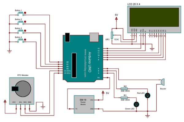
Circuit Diagram -Arduino RFID Attendance System
Project Description
The full circuit diagram for interfacing RFID module to Arduino is shown above. The unique ID code in the RFID card is read by the circuit and the name of the corresponding person will be displayed on the 20 x 4 LCD display. TX pin of the RFID module is connected to the 0th pin (RX) of arduino. The Arduino receives data from the RFID module through this channel.
Read more: RFID Based Attendance System – Learn to Build Yourself
- How does the system record arrival and leaving times?
The system stores the arrival time when a valid card is swiped first and saves the leaving time when the same person swipes their tag again. - Where are the user time details saved?
The arrival and leaving time details of a user are saved in the EEPROM of the Arduino. - What happens if I want to export data to a cloud host?
The article suggests not using an 8051 series controller for this; instead, it recommends using AVR Atmega series controllers or Arduino for systems communicating with the internet. - Can only an administrator clear the stored data?
Yes, the option to clear data can be accessed only by the admin using their specific ID. - What information is displayed on the LCD screen?
The LCD displays the current time and date along with the name of the corresponding person whose unique ID code was read from the RFID card. - How is the total working hour calculated?
The system adds the time between the recorded arrival and leaving swipes to calculate and store the total working hours for each user. - Which pins connect the RFID module to the Arduino?
The TX pin of the RFID module is connected to the 0th pin (RX) of the Arduino to receive data. - Is this project suitable for hobby purposes?
Yes, such a system can be easily designed using Arduino for hobby purposes.
