Summary of RFID Based Access Control Using Arduino
This article details an RFID-based access control system built using an Arduino UNO board and an EM-18 reader module. The system identifies objects via unique ID tags, processes data through middleware, and controls a solenoid lock based on database authorization. It covers the circuit design, component specifications, PCB layout, and software steps required to read tag IDs and grant access.
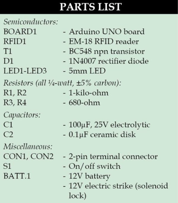
Parts used in the RFID Based Access Control System:
- Arduino UNO board
- ATmega328 microcontroller
- EM-18 RFID reader module
- RFID tag (credit-card size)
- Solenoid lock
- Solenoid driver transistor T1
- Base resistor R1
- 16MHz crystal oscillator
- USB connection cable
- AC-to-DC adaptor or battery
RFID is a non-contact, automatic identification technology that uses radio signals to identify, track, sort and detect a variety of objects including people, vehicles, goods and assets without the need for direct contact or line-of-sight contact (as found necessary in bar code technology). RFID technology can track movement of objects through a network of radio-enabled scanning devices over a distance of several metres. A device called RFID tag, or simply a tag, is a key component of the technology. These are actively used in RFID based access control systems implemented in offices all around.
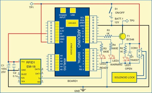
Circuit diagram of the access control system
An RFID system typically consists of three key elements:
1. An RFID tag, or transponder, that carries object-identifying data (unique ID code)
2. An RFID tag reader, or transceiver, that reads and writes tag data
3. A back-end database that stores records associated with tag contents
An RFID reader emits a low-level radio frequency magnetic field that energises the tag. The tag responds to the reader’s query and announces its presence via radio waves, transmitting its unique identification data. This data is decoded by the reader and passed to the local application system via middleware. The middleware acts as an interface between the reader and the RFID application system. The system then searches and matches the identity code with information stored in the host database or backend system.
In this way, accessibility or authorisation for further processing can be granted or refused, depending on results received by the reader and processed by the database.
RFID based access control circuit and working
Fig. 1 shows the circuit of RFID based access control using Arduino board. The circuit is built around Arduino UNO board (Board1), RFID reader module (RFID1), solenoid lock and a few other components.
Arduino UNO board
Arduino is an open source electronics prototyping platform based on flexible, easy-to-use hardware and software (called sketch). It is intended for artists, designers, hobbyists and anyone interested in creating interactive objects or environments.
Arduino UNO is a board based on ATmega328 microcontroller. It consists of 14 digital input/output pins, six analogue inputs, a USB connection for programming the on-board microcontroller, power jack, an ICSP header and a reset button. It is operated with a 16MHz crystal oscillator and contains everything needed to support the microcontroller. It is very easy to use as the user simply needs to connect it to a computer with a USB cable or power it with an AC-to-DC adaptor or battery to get started. The microcontroller on the board is programmed using Arduino programming language and Arduino development environment.
RFID reader module
RFID tags
Pin 0 (RX) of Board1 is connected to pin 7 (TX) of RFID1. Pin 10 of the board is connected to solenoid driver transistor T1 through base resistor R1. When pin 10 goes high, T1 conducts and solenoid is activated, which means lock is opened.
RFID reader module
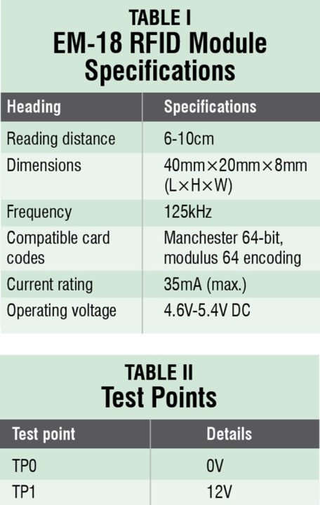
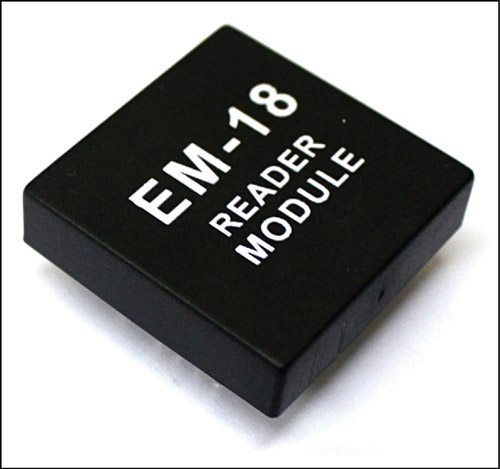
In this project we used EM-18 RFID reader module (Fig. 2) operating at 125kHz. The module comes with an on-chip antenna and can be powered with a 5V power supply. The transmit pin (TX) of the module should be connected to receive pin (RX) of Arduino UNO board. Some specifications of the module are listed in Table I.
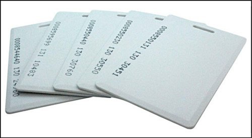
RFID tag
An RFID tag is a smooth card of credit-card size (Fig. 3), which is read by an RFID reader. It works at 125kHz and comes with a unique 32-bit ID. Normally, each tag has a unique ID number which cannot be changed. You can find out its unique ID through software.
Software
The software for this project is written in Arduino programming language. The Arduino UNO is programmed using Arduino IDE software. Atmega328 on Arduino UNO comes with a boot loader that allows you to upload new code to it without the use of external hardware programmer. It communicates using STK500 protocol. You can also bypass the boot loader and program the microcontroller through in-circuit serial programming (ICSP) header, but with boot loader the programming is quick and easy.
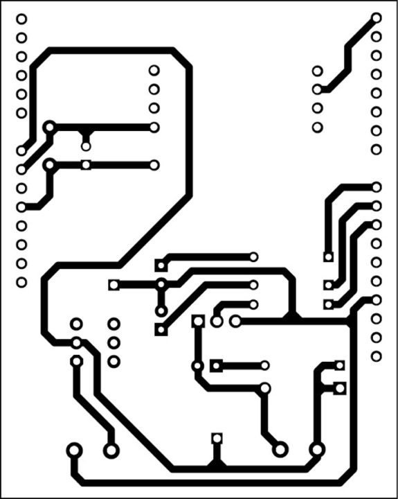
An single side PCB layout for the circuit
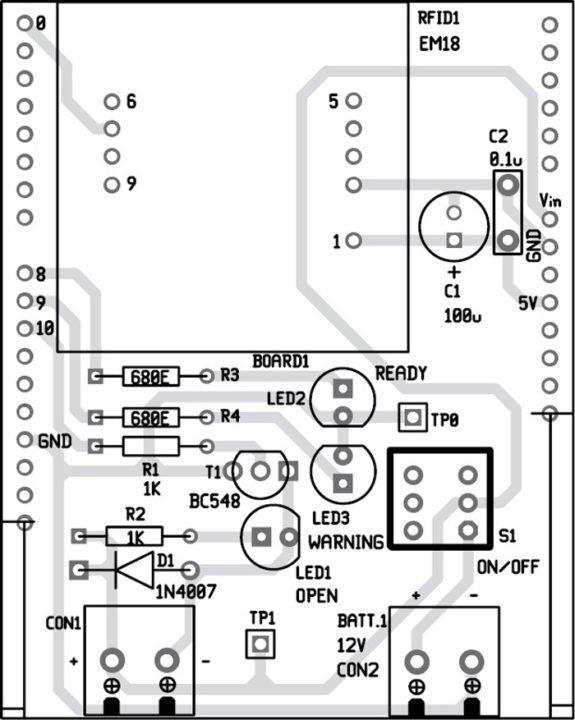
Component layout for the PCB
Download PCB Layout and component layout PDFs: click here
Download source code: click here
There are two sketch software codes for this application: ReadTag.ino for reading the tag’s unique ID and AccessControl.ino for the main application.
Reading tag ID
To read the tag’s unique ID, first you need to upload ReadTag.ino sketch into Arduino board by following the steps given below:
1. Connect TX pin of RFID1 to RX pin of Board1 as shown in the Fig. 1
2. Launch Arduino IDE. Connect Board1 to your PC and select the correct serial COM port and Board from Tools menu. Open ReadTag.ino sketch and compile it using Arduino IDE.
3. Burn ReadTag.ino sketch into the microcontroller in Arduino board
4. Open Serial Monitor from Tools menu in Arduino IDE
5. Hold RFID tag close to RFID1
6. Note down the tag ID shown on the Serial Monitor window. This ID will be used in the sketch later in the main application
Read More Detail:RFID Based Access Control Using Arduino
- What is the primary function of RFID technology?
RFID uses radio signals to identify, track, sort, and detect objects without direct contact or line-of-sight. - Can an RFID system work without line-of-sight contact?
Yes, unlike bar codes, RFID does not require direct contact or line-of-sight to function. - How does the solenoid lock get activated in this circuit?
The solenoid activates when pin 10 goes high, causing transistor T1 to conduct. - What frequency does the EM-18 RFID reader module operate at?
The EM-18 module operates at 125kHz. - What type of ID code does the RFID tag carry?
The tag carries a unique 32-bit ID code that cannot be changed. - Which software is used to program the Arduino UNO board?
The Arduino programming language and Arduino IDE software are used for programming. - What protocol does the ATmega328 use to communicate during programming?
The microcontroller communicates using the STK500 protocol via the boot loader. - How can you find out the unique ID of an RFID tag?
You can find the unique ID by uploading the ReadTag.ino sketch and checking the Serial Monitor window. - What are the two main sketch files provided for this application?
The two sketches are ReadTag.ino for reading the ID and AccessControl.ino for the main application.