
Summary of RESTORING A VINTAGE IBM I/O TESTER
This article details the restoration of a 1965 vintage IBM I/O Tester by CuriousMarc and his team. Originally designed to debug IBM System/360 peripherals like printers and storage devices, the portable rig uses indicator lights and paper overlays to monitor data registers and transfer statuses. The restoration involved powering the unit with 24 VAC, replacing burned-out lamps, repairing lamp assemblies, fixing toggle switches with guides and contact cleaner, and reusing original documentation. Currently, the device serves as a retro clock while awaiting potential future operational use.
Parts used in the Vintage IBM I/O Tester Restoration:
- Vintage IBM I/O Tester (circa 1965)
- 104-pin connectors
- Paper overlays
- Ninety indicator lights (blinkenlights)
- Lamp assemblies
- Toggle switches
- Contact cleaner
- New switch guides
- Replacement lamps
- Documentation for deciphering functionality
By now, [CuriousMarc] and his team of volunteers are well versed in 1960s hardware restoration. So when a vintage IBM I/O Tester came into their possession, a full machine makeover was all but inevitable.
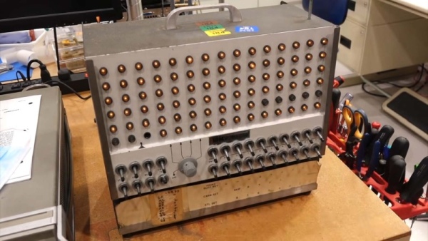
The I/O Tester dates from around 1965, which roughly coincides with the introduction of IBM’s lauded System/360 computer mainframe. In addition to the computer itself, business customers could order a variety of peripherals with their computing system. These included storage devices, printers, additional operator consoles, and so on. Since these peripherals shared the same I/O design, a portable hardware testing rig was a sensible design choice. One portable low-voltage tester could be paired with any number of IBM peripherals, doing away with the need to have unique debugging panels on every piece of computing hardware.
Fast forward to the present day, and the IBM I/O Tester looks positively antique with its blinkenlight lamp panel and switches. To use the tester, simply connect up one (or both) of its chunky 104-pin connectors to your IBM peripheral of choice, insert the accompanying paper overlay, and voilà. Operators could then observe the status of the many lamps to evaluate the inner digital workings of the connected peripheral. Depending on the connected hardware, the tester could reveal the contents of data registers, printing status, disk and tape transfer status, and probably much more. The purpose of the tester’s ninety indicator lights is completely dependent on the attached peripheral, and the paired paper overlays are essential to comprehend their meaning.
After [Ken Shirriff] deciphered the documentation, it wasn’t long before the tester could be powered up using 24 VAC (normally supplied by the equipment being tested). Several burned out lamps were noted for replacement. The lamp assemblies required minor surgery due to a dubious design choice, and at least one of the toggle switches needed a new guide and a heavy dose of contact cleaner before it came back to life.
For the moment, [CuriousMarc] is using the blinkenlights panel as a surprisingly striking retro clock. With a literal truckload of vintage IBM hardware sitting in his storage, it’ll be exciting to see whether this restored tester will be pulled back into operational service someday. Readers should also check out our coverage of his previous major project, restoring an Apollo Guidance Computer.
Source: RESTORING A VINTAGE IBM I/O TESTER
-
What was the primary purpose of the IBM I/O Tester?
The tester was designed to evaluate the inner digital workings of various IBM peripherals like storage devices and printers using a single portable low-voltage rig. -
How did operators interpret the status of the indicator lights?
Operators used accompanying paper overlays paired with the specific attached peripheral to comprehend the meaning of the ninety indicator lights. -
What voltage is required to power up the restored tester?
The tester can be powered up using 24 VAC, which is normally supplied by the equipment being tested. -
Which components required replacement during the restoration process?
Burned out lamps were noted for replacement during the project. -
How were the lamp assemblies repaired?
The lamp assemblies required minor surgery due to a dubious design choice identified during the restoration. -
What steps were taken to fix the malfunctioning toggle switches?
At least one toggle switch needed a new guide and a heavy dose of contact cleaner before it functioned correctly. -
What information could the tester reveal about connected hardware?
Depending on the hardware, the tester could reveal data register contents, printing status, and disk or tape transfer status. -
Is the restored tester currently in operational service?
For the moment, the blinkenlights panel is being used as a retro clock rather than its original operational service.
