Summary of Remote Controlled Robot Using Arduino and T.V. Remote
This project demonstrates building a remote-controlled car using an Arduino Uno and a standard TV or AC remote. The system utilizes an IR receiver to detect infrared signals emitted by the remote, which are then processed by the Arduino to control two DC motors via an L293D driver. The tutorial covers hardware assembly, library installation, and mapping specific remote button codes to movement commands like forward, backward, left, right, and braking.
Parts used in the Remote Controlled Car:
- Arduino Uno
- USB cable
- Breadboard
- 100rpm dc motors
- IR receiver (SM0038 or TSOP1738)
- L293D motor driver IC
- Jumper wires
- Chassis and wheels
- 9V batteries (2 nos)
- Battery clips
This remote controlled car can be moved around using practically any kind of remote such as TV,AC etc.
It makes use of the fact that the remote emits IR(infrared).
This property is made use of by using an IR receiver,which is a very cheap sensor.
In this instructable you will learn how to
- Interface IR receiver to Arduino.
- Interface 2 motors to Arduino.
- Combine the above 2 setups.
Note:This remote controlled car has a disadvantage of not work outside in sunlight.
Note:For those of you looking to download all the code, schematics and other pictures at one place and would prefer to use GitHub ,look at the end of this instructable.
Step 1: Materials Required
- Arduino Uno and USB cable
- Arduino software
- Breadboard
- 100rpm dc motors
- IR receiver(SM0038 or TSOP1738)
- L293D motor driver IC
- Jumper wires
- Chassis and wheels
- 9V batteries(2 nos)
- Battery clips
Total cost of materials:Rs 600=$ 9(excluding cost of Arduino)
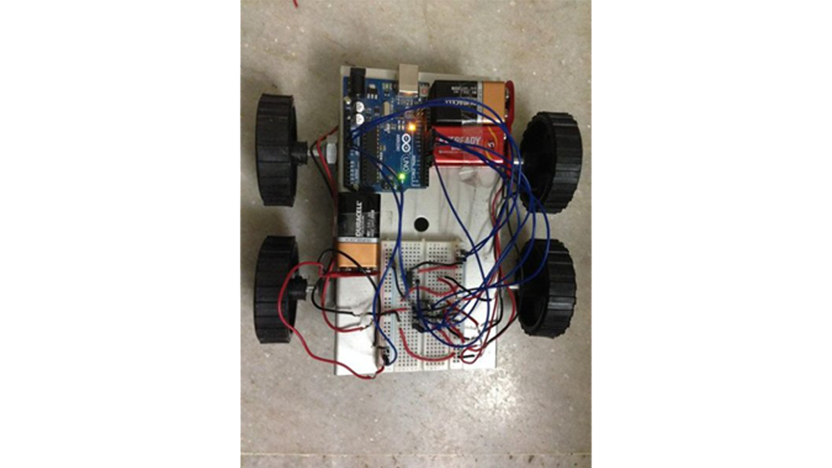
Step 2: Assembly
Fix the wheels to the chassis.
Attach the 2 motors to the back wheels and use dummies for the front.
Make holes on the chassis and fix Arduino using screws.
Fix the breadboard by using the double sided tape provided on it.
Mount the L293D on the breadboard with notch facing front.
Step 3: IR Receiver Connections
Facing the notch on the receiver, the connections from left to right are
- left pin-ground.
- middle pin-5V.
- right pin-digital pin 6 on Arduino.
Refer to the schematic for more details.
Step 4: Saving the IR Library
Go to the following link-
https://drive.google.com/open?id=0B621iZr0p0N_WUVm…
Save the files within a folder named IRremote and save the folder in the libraries directory of your Arduino IDE i.e. arduino-1.0.6>libraries folder as IRremote.
Step 5: Finding Hexadecimal Values of Remote Keys
1.Upload the given code into the Arduino
2.Open the serial monitor.
3.Press different remote keys and obtain their hexadecimal values.(Note that the values will not be obtained with 0x which represents hexadecimal also some values are obtained in middle like FFFFFFFF, ignore them).
Here I have obtained the values of the front,back,left,right and middle keys which are
front=0x80BF53AC
back=0x80BF4BB4
left=0x80BF9966
right=0x80BF837C
middle=0x80BF738C
These values of these buttons are mapped to move front,move back,move left,move right and brake respectively.
Read More: Remote Controlled Robot Using Arduino and T.V. Remote
- How does this remote controlled car work?
The car uses an IR receiver to detect infrared signals emitted by any kind of remote such as a TV or AC. - What is the disadvantage of this project?
This remote controlled car has a disadvantage of not working outside in sunlight. - Can I use a TV remote for this project?
Yes, you can move the car around using practically any kind of remote such as a TV or AC remote. - Which motor driver IC is used in the assembly?
The L293D motor driver IC is mounted on the breadboard to interface the 2 motors with the Arduino. - How do I find the hexadecimal values of remote keys?
You must upload the given code, open the serial monitor, press different remote keys, and obtain their hexadecimal values. - Where should I save the IRremote library folder?
Save the folder named IRremote in the libraries directory of your Arduino IDE. - What is the pin configuration for the IR receiver?
The left pin connects to ground, the middle pin to 5V, and the right pin to digital pin 6 on the Arduino. - Does the article provide code for download?
Yes, you can look at the end of the instructable to find links to download all code, schematics, and pictures from GitHub.