Every maker at least once make or tries to make RC Car.
RC Cars are widely available yet the joy of playing with the one you made yourself can’t be compared with the bought one.
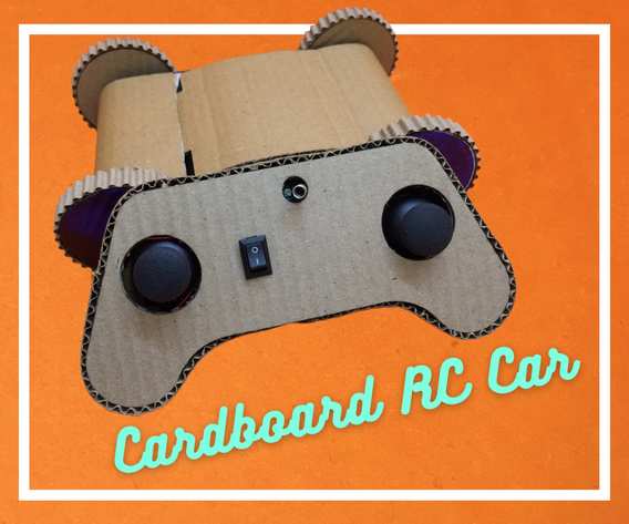
So I decided to make a Wireless RC Car with the easiest available material i.e. Cardboard.
No need for a 3D Printer, just grab some scrap Cardboard, a cutter & some glue, and let’s build our own RC Car.
Supplies
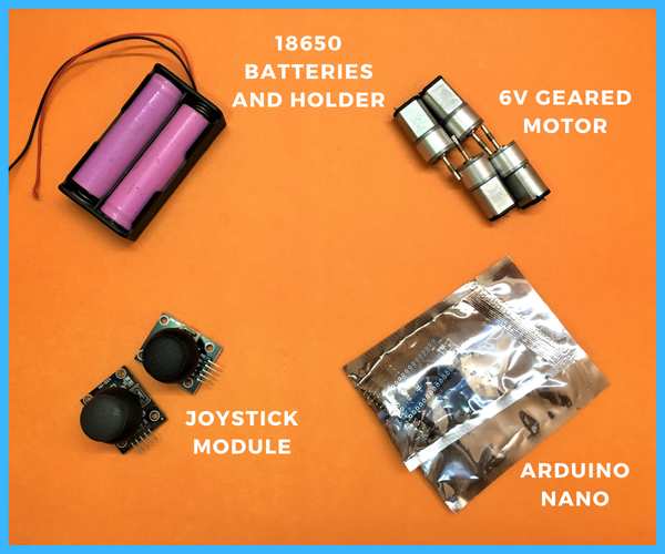
Components
- 2 x 18650 Batteries
- 1 x Lipo Battery
- 1 x 18650 Battery Holder
- 2 x On/Off switch
- 2 x Joystick
- 4 x 6V Motors
- 2 x Arduino Nano
- 6 x Screw Terminal
- 2 x HC-12 Transceiver Module
- 1 x 7805 voltage Regulator
- 4 x L9110s Motor Driver IC
- 1 x 3V to 5V Boost Converter 3Pin IC
- Female Header Pins
Software
- Arduino IDE
Hardware
- Double-Sided Tape
- Glue
- Cutter
- Scale
- Wires
- Soldering Iron
Step 1: Circuit Designing
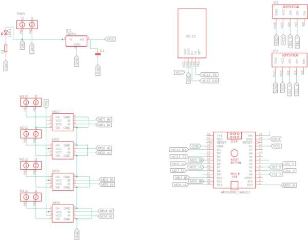
I have designed the Circuit in AutoCAD Eagle CAD.
The Circuit is designed in such a way the same PCB could be used for both transmitter and receiver of the RC Car.
The Motor Driver used is an L9110s controlled by Arduino Nano
The Telemetry module of choice is HC-12 as it works on UART and is quite easy to use.
In the Receiver board i.e. the board which is used by the RC Car will contain the motor driver and Arduino but not the joystick and the PCB Board on the Transmitter Side i.e. on the Remote Controller will be populated with Joystick whose pads are on the back side of the PCB.
Step 2: PCB Manufacturing
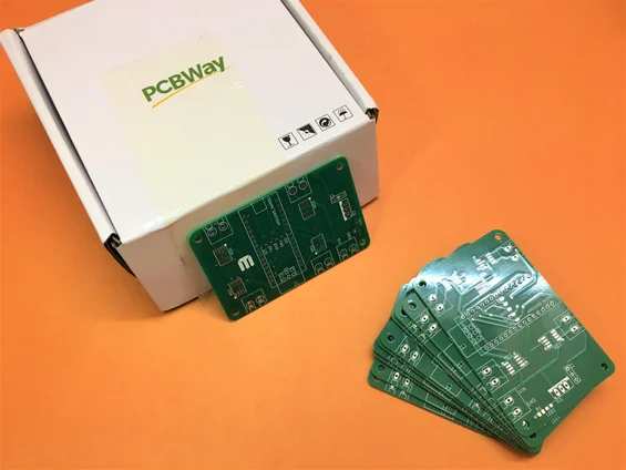
After creating the schematic and board design, rather than troubling myself with homemade PCBs, I generated the Gerber File (you can download it from this link) and ordered from the quick PCB Prototyping service of PCBWay.com, and within a few days 10 pcs of professional-made PCBs arrived at my home.
Step 3: PCB Assembly
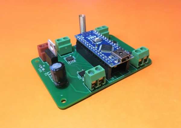
Assemble the PCB for Reciever as well as Transmitter both will include Arduino Nano and HC-12 Module.
HC12 Module will lie in between the Female Header pins of the Arduino Nano, so make such you attach the Header Pins first, and before soldering the header Pins, insert the HC-12 Module to space out the Header, then solder the female header Pins and HC-12. Otherwise, it may be difficult to insert the HC12 Module later in between the Header Pins.
Then solder the SMD Components such as Motor Driver, Resistor, LED, and in the end add Through Hole Components such as Screw Terminal, Capacitor, and 7805 Regulator for Receiver side and 3V to 5V Boost Converter IC for the Transmitter side PCB.
Step 4: Motors Preparation
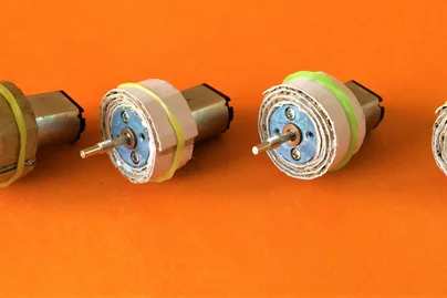
To attach the motor to the cardboard, i.e., to the side panel of the RC Car body, we will first wrap a strip of cardboard to the motor round section and thicken its border and create a surface upon which glue can adhere.
To attach the stip, first, add a layer of double-sided tape.
Then stick the stip of cardboard to the double-sided tape.
Then use white glue to stick further layers of cardboard and make the overall radius up to 25mm.
While the glue is drying, you can bind a rubber band around it, so the cardboard doesn’t peel away.
Step 5: Motor Mounting on Side Panel
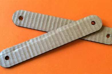
For the side panel, you can cut two strips of 28mm and a hole of 5mm at both ends. The DXF file for the side panel is attached below. You can take a printout of this DXF file for reference.
After the motor strips are dried, stick those upon this panel using white glue and secure them using some clips while it is drying.
After the motor’s stips are dried, attach the wires to the motors.
Step 6: Preparing Wheels
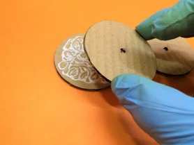
To Make the Wheels we are going to stack 4 layers of cardboard cut in a circular shape.
Each Cardboard Layer is 4mm leading to 16mm of Wheel Base.
Out of 4 layers, 3 layers will contain Hole and one will be without a hole and it will be used as the base i.e. the outer surface.
Later we will attach the motors to this hole.
Use some white glue to stack 4 layers of cardboard and let it dry.
Make 4 such wheels.
Step 7: Finalizing the Wheels
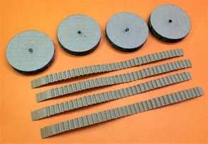
After the Wheels are dried we can attach some outer ridges to the wheels for better aesthetics.
to create the ridges take stips of corrugated cardboard pealed in one layer.
Remote the corrugation from the end of the cardboard strips.
Now use some white glue to stick the strips to the wheels as shown in the images above.
Tie any wire or thread around the wheel to secure the stips to the wheels while the glue is drying.
Step 8: Preparing the RC Car Body
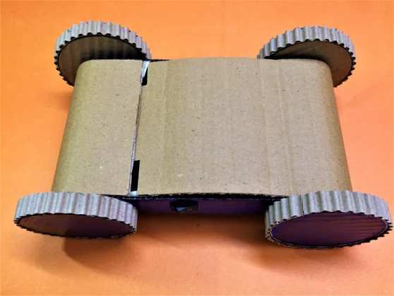
To prepare the body of the RC Car, we will take a 40cmm X 9 cm strip of corrugated Cardboard and wrap it around the side panel we created in the steps above.
Before attaching the side panels, add a rectangular piece of the same corrugated Cardboard as a base for the electronics we will be adding later.
Then place the Motor Side Panel on both sides of the strip.
Use white glue to secure the body to the side panel.
Use some extra cardboard strips with glue to attach the base to the side panel.
Make sure the body is securely attached to the side panels.
Create a cut on the upper flange so it can be closed by inserting on the top.
Step 9: Adding Control Electronics to RC Car
When the Body is complete we can move to add the electronics to our RC Car.
First Attach all the Motors Wires to the PCB.
Make sure left side Motors are attached to MD1 and MD3 and right side Motor to MD2 and MD4.
Then Attach the Battery Holder in Series with the On/Off Switch and then Attach it to the Vin and GND Terminals on the PCB.
After that insert the Holder and PCB inside the RC Car Body.
Secure them using some double Sided Tape.
Step 10: Adding the Wheels
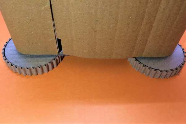
Place the wheels on the table and add some glue gun near the hole and then insert the Motor shart into the hole and hold the body upright until the glue gun is stiff.
Repeat the same on the other side.
Step 11: Programming the RC Car
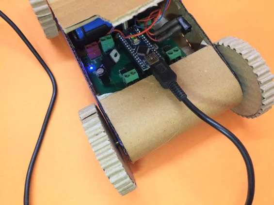
Programming the Arduino Nano will be the easiest step out of all the steps.
Just grab a mini USB cable and upload the code provided below into the microcontroller.
The only library you will need is Software Serial which is mostly preloaded with the Arduino IDE.
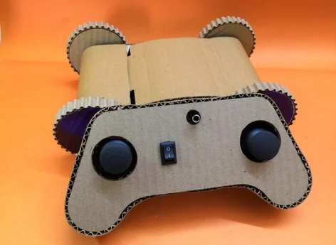
Step 12: Enclosure for the Remote Control
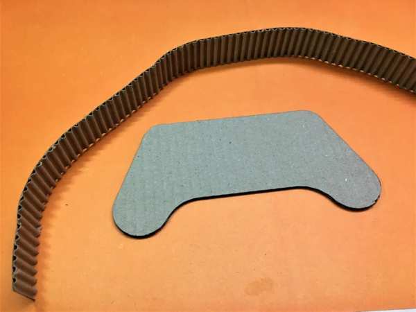
For the Remote controller, we will use a base in the shape of a Joystick and attach a corrugated stip on the edges of the shape.
To attach the stip first attach some semi-peeled strips of a corrugated sheet to the base as can be seen in the image above.
Then with the help of these semi-peeled sheets attach the main strip to the border of the base.
Use some clips to secure them together until the glue dries.
Step 13: Circuit for Remote Control
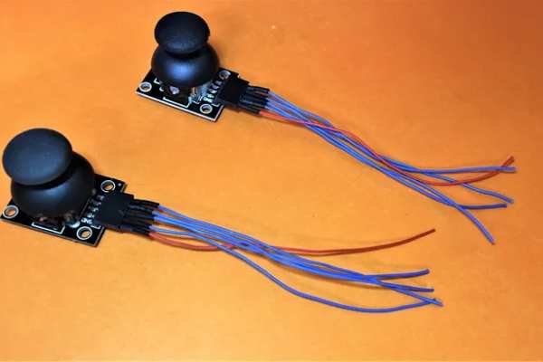
Connect the Two Joysticks to the Arduino Boards.
The pads for Joystick are on the back of the PCB.
To make the connectors for the joystick I use 5 Pins female headers and solder wires of 10cm to it.
Step 14: Assemble the Remote Control
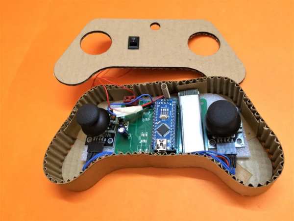
As the base is prepared it’s time to add the electronics and cover it.
Place the Electronics over a foam sheet so it will help reduce the vibration while using the joysticks and also help in easily placing and securing the components in the body.
Then place the Components inside the body and attach the battery and switch.
There is a hole on the top cover for the On/Off Switch and the HC-12 antenna.
Step 15: Programming the Remote Control
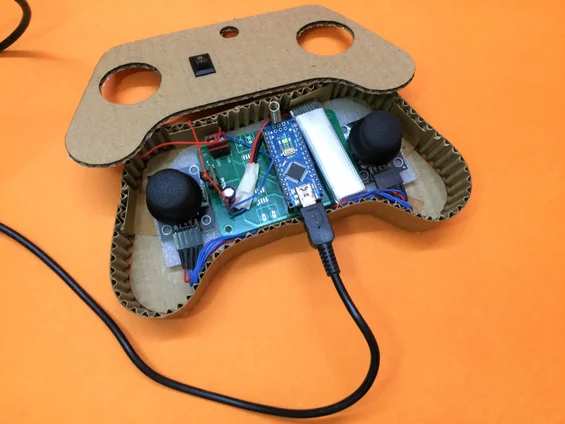
Programming the Arduino Nano will be the easiest step out of all the steps.
Just grab a mini USB cable and upload the code provided below into the microcontroller.
The only library you will need is Software Serial which is mostly preloaded with the Arduino IDE.
All the pins are defined on the top of the Code and change them as it suits you to change the direction and rotation of the motor.
Step 16: Play Time
Now that everything is prepared….it’s PlayTime.
Go and enjoy the ride with your self make RC Car.
If you made this project do share it below and if you face any issues during the build message me, I would love to help you out.
Source: Remote Controlled Car Using Cardboard
