
Summary of Remote Control Traffic Lights using Arduino Yun with Proteus Simulation
Remote Control Traffic Lights is a beginner-friendly IoT project using an Arduino Yun and Proteus simulation to let a mobile device (IotBuilder) remotely advance or reverse a traffic-light state machine. The controller listens for two IoT triggers, updates a state variable (with wraparound), and sets pins IO5, IO6, and IO7 to drive red, yellow, and green outputs across five defined states for testing and learning embedded systems, output switching, and simulation-based development.
Parts used in the Remote Control Traffic Lights:
- Arduino Yun
- Physical Traffic Lights block / three light outputs
- IotBuilder mobile control interface
- Output pins IO5, IO6, IO7
- Reset and status LED section
- USB / power interface (Arduino Yun)
- Supporting connection headers and serial interface block
Introduction
Remote Control Traffic Lights is a simple but practical microcontroller project built around the Arduino Yun and designed for Proteus simulation. Based on the material you provided, this project lets a user control a traffic light sequence from a mobile device through IotBuilder, making it a nice example of Internet of Things, embedded systems, and DIY electronics working together. The idea is straightforward: a mobile interface sends commands, and the controller updates the red, yellow, and green traffic light outputs. It is useful for learning how remote control logic, output switching, and simulation-based testing work in a compact practical electronics project. It also makes a good starter project for understanding the working principle of a connected traffic control system.
How the Project Works (Overview)
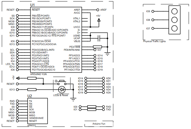
This project uses an Arduino Yun as the main controller and drives a set of three traffic light outputs connected in the schematic as physical traffic lights. The logic is based on a variable called state, and mobile control is handled using two IoT triggers: one moves the system forward through traffic states, and the other moves it backward. The flowchart shows that the controller starts by configuring the output pins, then waits for requests from the remote/mobile side. When a command is received, the system updates the traffic state and switches the LEDs accordingly. The project cycles across multiple traffic conditions, including red, red+yellow, green, yellow, and all-off.
Workflow Explanation
1. Mobile Control Layer
The project description states that the traffic lights are controlled from a mobile device using IotBuilder. The flowchart identifies two triggers: IotBtn1 for forward state movement and IotBtn2 for backward state movement.
2. Arduino Yun Controller
The Arduino Yun acts as the processing unit. In setup, the controller initializes output pins, then continuously listens for incoming requests. The flowchart explicitly shows the controller waiting for requests with a timeout value of 1000.
3. Traffic State Logic
A state variable controls which light combination should be active. Pressing the forward button increments the state, while the backward button decrements it. Boundary logic is also present: when the state reaches 5 it wraps to 1, and when it goes below the valid range it returns to 4.
4. Output Section
From the flowchart and schematic, pins 5, 6, and 7 are used to drive the traffic light outputs. The physical traffic lights in the schematic are connected to IO5, IO6, and IO7, which match the control logic shown in the flowchart.
Key Features
-
Mobile-based remote control using IotBuilder
-
Built on the Arduino Yun platform
-
Supports forward and backward traffic state switching
-
Multi-state traffic light behavior using digital outputs
-
Designed for easy Proteus simulation
-
Uses clear output mapping for red, yellow, and green lights
-
Includes state wraparound logic for smooth operation
-
Suitable for learning embedded systems and microcontroller project design principles
Components Used
Based on the description, schematic, and flowchart, the project uses:
-
Arduino Yun
-
Physical Traffic Lights block / three light outputs
-
IotBuilder mobile control interface
-
Output pins IO5, IO6, IO7
-
Reset and status LED section shown in the schematic
-
USB / power interface as part of the Arduino Yun hardware
-
Supporting connection headers and serial interface block visible in the schematic
Applications
This type of system can be used in several practical and educational areas:
-
Traffic light logic demonstration in classrooms and labs
-
IoT-based control system training
-
Embedded systems experimentation in Proteus simulation
-
Smart signal control concept demonstrations
-
Remote appliance or indicator control projects
-
Beginner-friendly DIY electronics and automation learning
Explanation of Code
No raw source code was included in the material you provided, so the explanation below is derived only from the project description, schematic, and flowchart.
The firmware logic appears to be organized around a simple state machine. During setup, the controller configures the relevant digital pins as outputs. Inside the main loop, the system waits for remote commands from the IoT interface. When the forward trigger is received, the state value increases; when the backward trigger is received, the state value decreases. A traffic-handling routine then checks the current state and writes HIGH or LOW values to the traffic light pins.
The flowchart shows five output conditions:
-
State 1: pin 5 ON, pin 6 OFF, pin 7 OFF
-
State 2: pin 5 ON, pin 6 ON, pin 7 OFF
-
State 3: pin 5 OFF, pin 6 OFF, pin 7 ON
-
State 4: pin 5 OFF, pin 6 ON, pin 7 OFF
-
State 0/default: pin 5 OFF, pin 6 OFF, pin 7 OFF
This means the code most likely contains:
-
pin initialization logic
-
IoT request handling
-
a state counter
-
conditional digital output control
-
a function similar to
SetTrafficState()
Flowchart
Proteus Simulation
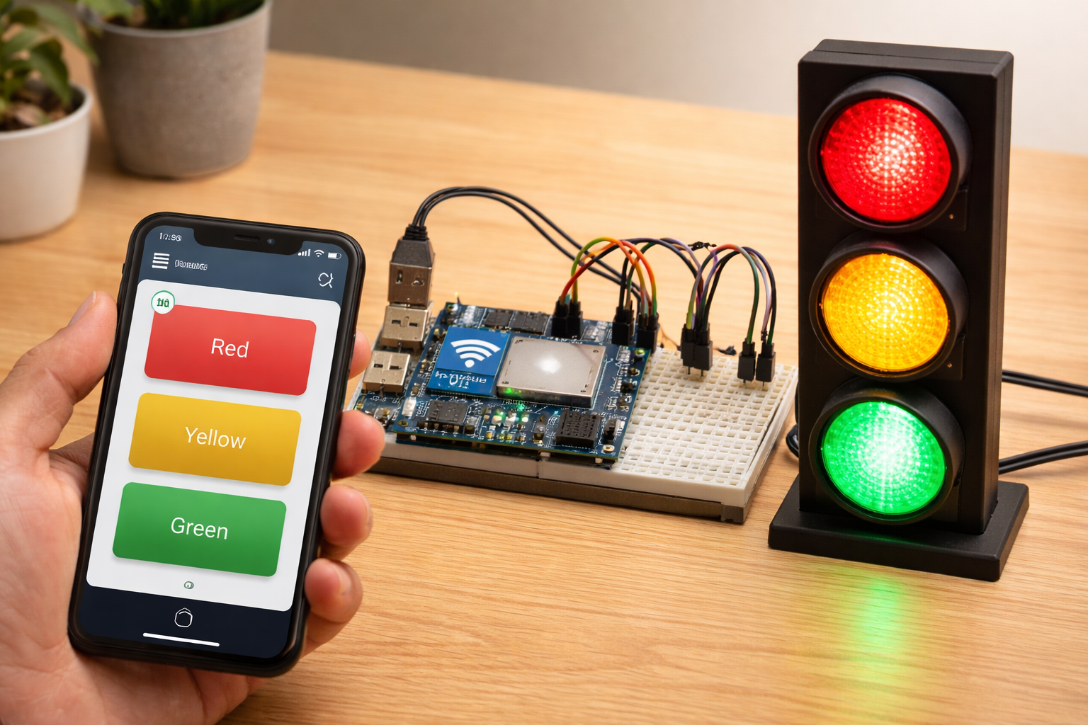
In Proteus simulation, this project behaves like a remotely controlled traffic light module. The Arduino Yun receives commands from the IoT control side, updates the internal traffic state, and changes the three output lines connected to the traffic light block. The simulation is useful because it allows the user to test the switching behavior of each traffic light state before moving to real hardware. From the provided flowchart, the system supports forward and backward state control, which makes it easy to verify each lighting sequence interactively.
Conclusion
Remote Control Traffic Lights using Arduino Yun with Proteus Simulation is a neat beginner-friendly embedded systems project that shows how mobile-based control can be connected to practical output logic. Even with a simple design, it teaches useful concepts like state control, output switching, IoT interaction, and simulation testing. It is a solid project for anyone exploring DIY electronics, firmware logic, and real-world microcontroller project design.
Complete File
Remote Control Traffic Lights using Arduino Yun with Proteus Simulation
- How is the traffic light controlled remotely?
The traffic light is controlled from a mobile device using IotBuilder triggers sent to the Arduino Yun. - Can the system move forward and backward through states?
Yes, two IoT triggers IotBtn1 and IotBtn2 move the system forward and backward through traffic states. - What pins drive the traffic light outputs?
Pins IO5, IO6, and IO7 are used to drive the red, yellow, and green outputs respectively. - Does the project include wraparound state logic?
Yes, when the state reaches 5 it wraps to 1 and below the valid range it returns to 4. - What are the defined traffic states?
The flowchart shows states: State 1 (pin5 ON), State 2 (pin5 and pin6 ON), State 3 (pin7 ON), State 4 (pin6 ON), and State 0/default (all OFF). - How does the Arduino Yun process commands?
The Arduino Yun initializes output pins, waits for IoT requests with a timeout of 1000, then updates the state and sets outputs accordingly. - Is the project suitable for Proteus simulation?
Yes, it is designed for Proteus simulation to test switching behavior before real hardware implementation. - What learning goals does the project support?
It teaches state control, output switching, IoT interaction, and simulation testing for embedded systems beginners.
