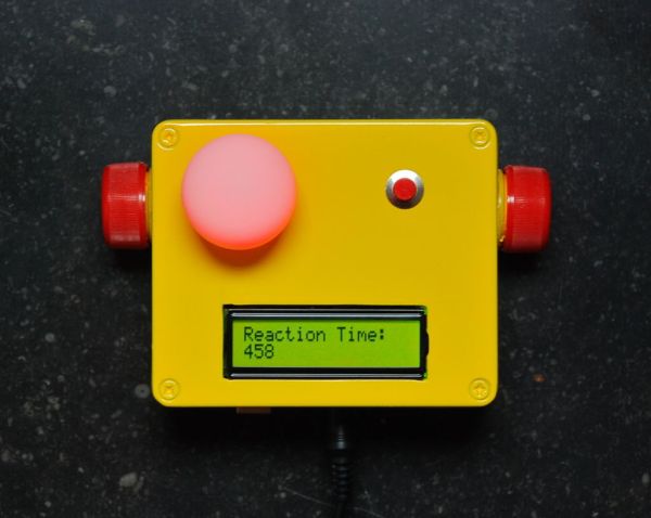
A month ago I knew nothing about Arduino and now…..my first project!
Looking back, this project combines allmost all of the tutorials that I have read in this short period: blinking LED, push button, piezo and LCD display. A useful project for every beginner!
I have made this device for some of my friends who have a hard time admitting how fast alcohol influences their driving abilities.
It will test you on three levels because they all have to do with driving a car safely:
- DECISION time.
- REACTION time
- Resistance to DISTRACTION.
The test starts as soon as you hold down the push button. When a red light appears, you should let go off the push button as soon as possible. Your reaction time will appear on the screen.
However, driving has to do with making fast decisions as well. So in random order you can get a green or blue light first (or multiples). You should not react to this and hold down the push button until the red light appears.
Finally, on occasions you will hear a short beep in between lights (just for fun). By now you are so tense to do well, that a simple distraction like a beep can and WILL set you off!!
A fun game with your dinner guests upon arrival and confronting upon leaving!
Step 1: What you need
- Arduino microcontroller (I have used an Uno).
- 1 RGB LED (you can use 3 separate ones if you like).
- 4 resistors (220 ohm).
- LCD Display
- Piezo speaker
- Breadboard.
- Push button.
- Wires.
- Ping pong ball (optional).
- Box.
Step 2: The hardware.
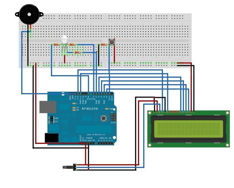
For the experienced Arduino user this total view makes immediate sense. However, if you’re a beginner just like me, a breakdown in steps can be useful.
Drawings were made with software by “Fritzing” (http://fritzing.org).
I have used a RGB Led with a common Anode (3 Cathodes: R, G, B). Therefore the setup may seem a bit ackward. The consequence is that in the sketch (step 3): HIGH=off and LOW=on.
Step 3: The Sketch.
To make the test even more unpredictable, I have added two other features:
- The duration of a light is random (within some limits).
- The pause between lights is random as well (within some limits).
This is to avoid that people get a feel of the “rhythm” of the test. Making it predictable.
You can make the test harder by increasing these intervals. The sketch is in the TEXT file below.
 ADRTT.txt3 KB
- Arduino
- 1 RGB LED
- 4 resistors (220 ohm).
- LCD Display
- Piezo speaker
- Breadboard.


