Summary of Pulse Sensor and Arduino – Interfacing
This article explains how to interface a plug-and-play Pulse Sensor with an Arduino to measure heart rate. The sensor detects heartbeat by measuring light reflection changes caused by blood volume fluctuations in capillary vessels. It features three pins (GND, VCC, A0) and includes a central LED for detection along with noise elimination circuitry.
Parts used in the Pulse Sensor and Arduino Interfacing Project:
- Pulse Sensor module
- Arduino board
- GND pin
- VCC pin
- A0 analog pin
- LED
- Noise elimination circuitry
In this article, we are going to interface a Pulse Sensor with Arduino. The pulse sensor we are going to use is a plug and play heart rate sensor. This sensor is quite easy to use and operate. Place your finger on top of the sensor and it will sense the heartbeat by measuring the change in light from the expansion of capillary blood vessels.
Pin Out – Pulse Sensor
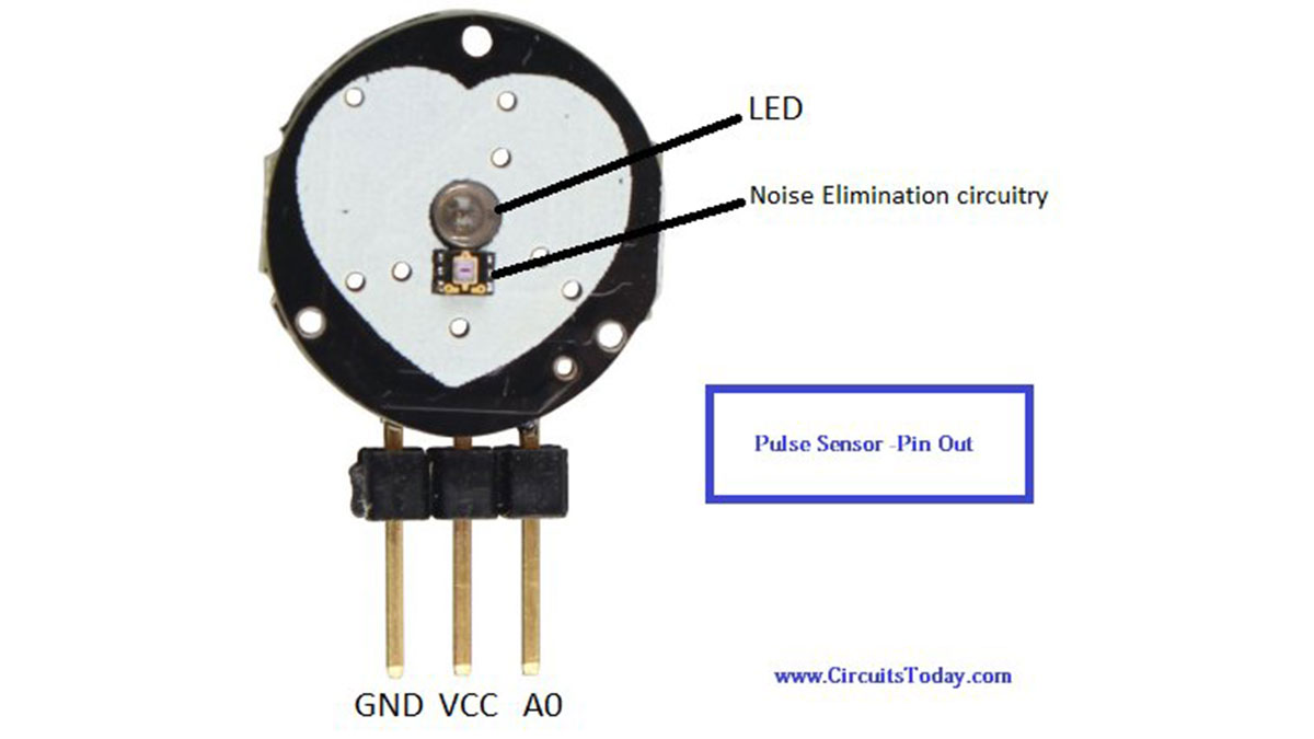
The pulse sensor has three pins which are as described below:
- GND: Ground Pin
- VCC: 5V or 3V Pin
- A0: Analog Pin
There is also a LED in the center of this sensor module which helps in detecting the heartbeat. Below the LED, there is a noise elimination circuitry which is supposed to keep away the noise from affecting the readings.
Working – Pulse Sensor
When a heartbeat occurs blood is pumped through the human body and gets squeezed into the capillary tissues. The volume of these capillary tissues increases as a result of the heartbeat. But in between the heartbeats (the time between two consecutive heartbeats,) this volume inside capillary tissues decreases. This change in volume between the heartbeats affects the amount of light that will transmit through these tissues. This change is very small but we can measure it with the help of Arduino.
The pulse sensor module has a light which helps in measuring the pulse rate. When we place the finger on the pulse sensor, the light reflected will change based on the volume of blood inside the capillary blood vessels. During a heartbeat, the volume inside the capillary blood vessels will be high. This affects the reflection of light and the light reflected at the time of a heartbeat will be less compared to that of the time during which there is no heartbeat (during the period of time when there is no heartbeat or the time period in between heartbeats, the volume inside the capillary vessels will be lesser. This will lead higher reflection of light). This variation in light transmission and reflection can be obtained as a pulse from the ouptput of pulse sensor. This pulse can be then coditioned to measure heartbeat and then programmed accordingly to read as heartbeat count.
Read More: Pulse Sensor and Arduino – Interfacing
- How does the pulse sensor sense the heartbeat?
It senses the heartbeat by measuring the change in light from the expansion of capillary blood vessels when blood is pumped through them. - What are the three pins on the pulse sensor?
The three pins are GND (Ground), VCC (5V or 3V), and A0 (Analog Pin). - Does the sensor module have a light source?
Yes, there is an LED in the center of the sensor module which helps in detecting the heartbeat. - How does blood volume affect light reflection?
During a heartbeat, increased blood volume leads to less reflected light, while between heartbeats, lower volume leads to higher reflected light. - Can the small change in light transmission be measured?
Yes, this very small change can be measured with the help of an Arduino. - What is the function of the noise elimination circuitry?
The noise elimination circuitry is supposed to keep away noise from affecting the readings. - How is the output from the pulse sensor processed?
The variation in light transmission and reflection is obtained as a pulse, conditioned to measure heartbeat, and programmed to read as a heartbeat count.