This project is an extension or remix of my original Portal Turret on Instructables (Portal-2-Turret-Gun). It can also be used as a cheap controller to control anything that uses the nRF24L01 radio chip. The LCD screen is particularly useful when customizing.
(It turns out to be quite useful in checking when my radios establish and lose connections with other nRF24L01’s on the “network”. I can walk around and watch the display screen show the connection status of the radios! Quite helpful for adjusting settings and verifying range!)
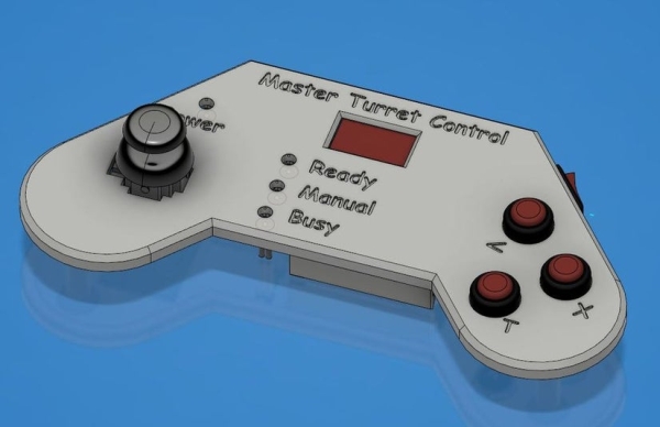
After I had completed the Portal Turret, I saw a short video clip of the Cara Mia opera scene at the end of Portal 2. I thought, “hey, I’ve built a few turrets now. I can do that!” Well, I had the turrets, but to make it work, they would now need to communicate with each other, or with some other device. After giving it some thought, and thinking that manual control would also be cool, I ended up deciding that I would build a Master Turret Controller, or an MTC.
Ok, so how to go about this? Well, I didn’t feel like modifying the turrets too much, so that was a constraint. I had some nRF24L01 radio chips which I hadn’t yet used, and thought that would keep in line with my goal of using inexpensive components and relying on mechanical design and code to make this work. I would have to build a controller and started mulling over what the controller would contain and what exactly I could do to the turrets. Cara Mia was already on the agenda, but what else?
Manual control: So once the wings are open, I would like to control the pitch and the pivot. 2 axes = a joystick, so joystick control and some push buttons. Push button 1 would fire the turret, and maybe push button 2 would make it say one of its sayings. Sounds good! Simple enough…
Chat: I recently saw the “Who’s on First” – Abbott and Costello routine again, and a light went off in my head! I would also make a sketch comedy routine using all of the sayings, using multiple turrets!! Ok, this one wasn’t fully figured out, but I’m sure I would get it sorted once my build was underway.
I also wanted this MTC to be wireless, so I opted for a simple 9V battery powered option and designed the controller to be powered by the mini-USB plug through the Nano at the back. Useful for updating too.
Step 1: Incorporating the Radio Into the Turrets
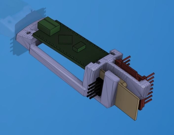
I first got the radio working with a few bare Nanos, to make sure I could make it work and send information between multiple devices. Once that was done, it was a matter of incorporating the radio into the existing turrets. Hmm, adding the physical PCB into the turret was pretty easy. I just modified the chip holder to include the nRF24L01, the Nano and the mp3 chip. Ok. One physical part modified, with some wiring.
The modified chip holder is already part of the turret printed parts now. I just deleted the non-radio option from the printed parts in that build. It won’t make a difference if someone wants to build the non-radio variant. Just don’t include the nRF24L01 radio chip.
Step 2: (Re)wiring of the Turrets
Uh oh…
This wasn’t looking good. I needed to add 5 connections to the Nano, and I was already low on available pins. After looking into this for a bit, I realized which connections took precedence, and recognized that to make this work, I would have to remap most of the existing Nano connections.
To those who want to make a “Radio Turret” and have already built the previous gen… Sorry…
Now, I’ve done this change a few times and it turns out that the process isn’t too bad. It does involve going back in, but I was able to undo the existing connections to the Nano and then reconnect to the appropriate pins without too much grief. I added the 7 wires for the radio chip to the nRF24L01 (5 comm wires, 3v and GND), then connected the other ends to the Nano.
More wires in there now though, so it makes that much more important to keep things tidy when routing the wires.
IMPORTANT: When assembling, make sure the wires don’t press on the Nano reset button on the board!! That happened to me on one and threw me for a needless loop!
So the turret build now has 2 wiring schematics: the old legacy “non-radio” option and the revised “radio Turret” option. If building a “non-radio” turret today, I would still use the radio schematic and code. Just delete or comment out the radio portions if that’s the chosen route, or not. The turret should still work on its own without the radio.
Step 3: MTC Electrical Components
Having the turrets sorted out, it was time to make an MTC.
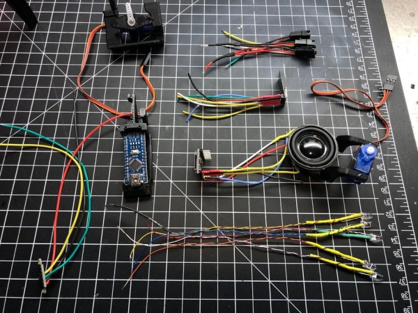
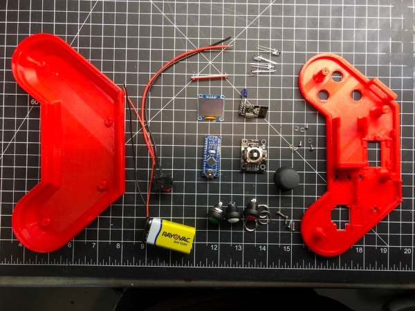
The MTC uses the following components, all sourced through Amazon or Baggood or Ali Express, etc. I’m showing the Amazon part numbers that I referenced for reference, since these items are commonly available and reasonably priced (and I didn’t have to wait 2+ weeks to get my hands on what I needed before I could start the mechanical design!)
- Arduino Nano 0.96” LCD, (SSD1306) I used the Blue/Yellow version
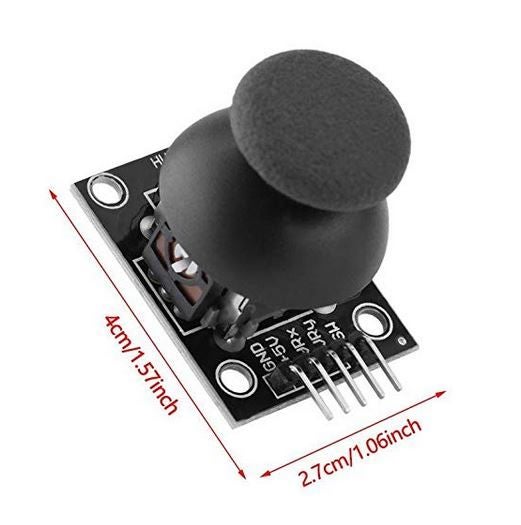
- Small Joystick (HW-504) 5V PS joystick module
- Toggle switch (dx-004) 22mm * 13mm
- Radio – (nRF24L01)
- 12mm pushbuttons (CLT1088 for coloured buttons, PBS-33B for black)
- 2 mm screws (M2 Self Tapping Screws Set, Cross Drive Pan Head assortment)
- 5mm LEDs of your choice for indicators. (Don’t use bright LEDs!!)
- Generic 9V battery connector with pigtails
- 9V battery (use a good one, not one of the dollar store varieties which can’t always supply enough power for these projects!)
- I used silicone sheathed wire. I like using it for these projects.
I originally used some bright LEDs, but found they were too good. They were blinding me! I ended up using some old, weak LEDs, and that made more sense for this application.
Step 4: 3D Printed Parts
I designed the MTC using Fusion, similar to the way I did the turret design.
The printed assembly only requires 3 parts:
- Top panel (version 1 or 2)
- Bottom housing
- LCD strap
The nRF chip, the Nano, the 9V battery, the toggle switch and the LEDs are installed in the top plate without fasteners. The LEDs just press in the plate and are held in place by tabs. They should just snap in, but don’t overdo it. The top plate is designed to snap-hold the Nano, and the nRF chip should go in gently. Careful with the nRF small tab; it is small and is bent back to open up and released to capture the chip. Even though its travel is limited, be gentle here.
The joystick and the LCD need 2mm screws (5mm long) to hold them to the top plate. The joystick PCB has large holes, so I felt I needed small washers to make sure the screws didn’t pull through.
I’ve found that the PCB’s the LCD’s come on vary slightly dimensionally from manufacturer to manufacturer, so I opted to use a simple strap to hold it in place instead of cleats or hooks.
Note that the LCD can be physically installed into the top plate either way, but the display only shows up fully through the opening in one orientation! For this reason, I’ve included a 2nd top plate option when using the split yellow/blue screen. One version has the yellow at the top, and the other will show the yellow at the bottom as shown in my photos.
For the single colour version LCD, it doesn’t matter which one is used as you can flip the display using software.
Since all the wiring is done on the top plate, the bottom is effectively just a cover held to the top plate with longer 2mm screws (qty:4).
Instead of a “battery door” option, I just incorporated the battery into the top plate. This means removing the 4 screws that hold the bottom to the top to change a battery, but since it can also be powered by USB cable, not the end of the world. The top plate is made with a 9V battery holder system that should be sturdy enough for repeated use, isn’t overly complicated but prevents the battery from moving around.
I printed the top plate in 2 colours as seen in the photos. I use a Prusa i3 Mk2 without the multi colour option, but use their colour print tool (https://www.prusaprinters.org/color-print/) to change colour partway through the process. Check the layer that the text stops and becomes solid, and make that the transition layer. Voila! Coloured text!
I printed the parts at 0.35mm layer height since there is no need for finer resolution on these flat parts. I also prefer the way it looks at this resolution. Oh, and it prints pretty quickly too!
Step 5: Electrical Assembly
The electrical components are all installed on the underside of the Top plate, and all wiring is done together. Push buttons and toggle have to be installed first, and the LCD, Nano, Joystick, nRF radio can all be pre-wired before being installed in the Top plate. I recommend this method of pre-wiring the individual components, then making the final connections to the Nano at the end. I also recommend uploading the sketch to a bare Nano first, before completing the wiring.
There is nothing more satisfying than switching the device on and watching it come to life as expected when finished!
The only electrical part prep required was to remove the header pins from the joystick to make it fit under the top plate. The LCD screen can be purchased with or without pins installed, and will work either way. The Nano should be selected without header pins.
Source: Portal 2 Turret – Master Turret Control