I have been trying to get my hands on a laser cutter for some time but they always seem out of reach. All the great things that can be done with a real laser cutter tickle the imagination.
I feel it’s time to share my latest project – a low cost laser engraver,. The workspace is a bit small but none the less it works and comes so cheap that most will be able to replicate the result. I did take a few shortcuts, as I feel I don’t have the knowledge to do all the electronics I opted for readymade but low cost in favor of trying to make my own (and most likely fail). All parts used are however easy to find.
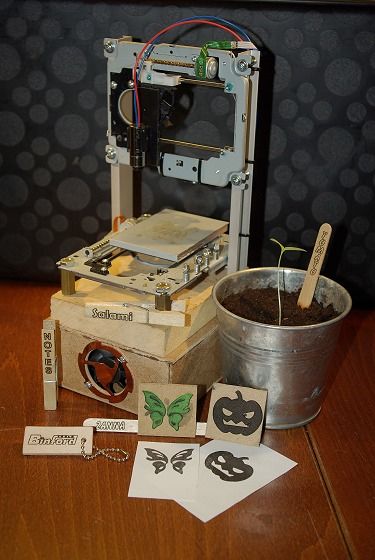
I am pleased with the end result even if there is room for improvements. The small size and low power is a bit limiting but I have made allot of fun things already. Paper cutouts, plant markers and stamps among some. The engraver itself might not fit in a pocket but the workspace limits what you can do with it to fit in the pocket.
A word of warning is in place . This instructable is using a ~200mW red laser. It might nut cut through chunks of wood but it will make you go blind if you are not careful. Never look into the beam, even reflections can be dangerous if focused. Please be careful.
Step 1: Acquire the Parts.
Most of the hardware comes from my junk bin. The aluminum profiles, the piece of MDF and various nuts, bolts and wires. But some things need to be acquired. Most of the electronics can be found over at Sparcfun and the rest on e-bay or a swap meet.
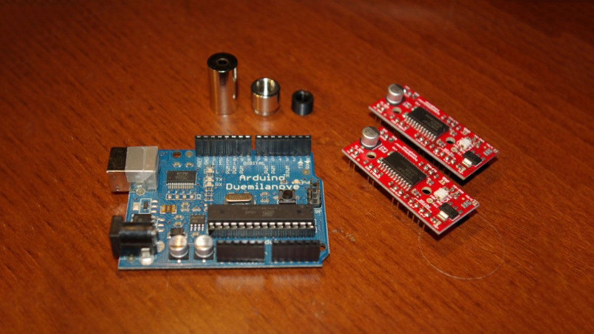
– Arduino – this is the heart of the control electronics.
– Easydrive – stepper driver.
– Two DVD-rom drivers – Maybe more if you’re unlucky, and at least one DVD-R to salvage the laser from.
– Laser housing – singles can be found on e-bay.
– Laser driver – There are lots of alternatives here, I use a simple LM317 based circuit.
– Various nuts, bolts and other building materials.
Step 2: Rip Apart the DVD-Roms.
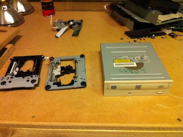
All you need from the DVD-Roms are the stepper motor assembly and one laser diode. I had a bit of bad luck and found that one of my DVD-Roms had a plastic assembly that would be very hard to work with. Thus I ripped apart three DVD-Roms and only used parts from two of them. It is pretty strait forward and most DVD-Roms I have opened works more or less the same way.
After removal of the screws at the bottom of the drive you can lift it of like a lid. Underneath you will most likely find two circuit boards and none of them are any use to us. But remember to salvage other useful parts that can be used for other projects. For example under the front circuit board there is a small dc motor worth saving. This is when it is time to remove the front together with the front of the tray; the front comes loose after you pull out the tray (just use a hairpin and the small hole in the front). The next step can include some screws and/or mild force. Remove the two circuit boards. Be careful with the ribbon cable to the stepper motor. If you turn the DVD-Rom right side up and remove the cover, you should find what we are looking for, the stepper motor assembly. Remove the screws and just lift it out.
Now that we have the assembly out it needs to be cleaned up a bit. Remove the spindle motor, it could be useful but I feel they are hard to drive and thus don’t keep them. They are usually hold in place by three very small screws but sometimes they are part of a larger assembly so be careful that removing it won’t compromise the two rods holding the lens.
The lens is another story, just remove it best possible way, we need a smooth surface to attach other parts to later. Be careful to not harm the DVDR laser diode. It can come to good use if you don’t want to buy a new powerful laser later. See the next step.
Step 3: Putting a Laser Together.
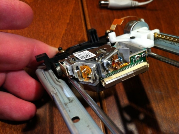
There are so many good instructables on this subject, I will just make this part a quick one and let the pictures do most of the talking.
Removing the laser from the DVDR is not hard but most lens assemblies look different. Locate the diodes (there will be two, one IR and one red) and remove them from the assembly. There are some optics and two magnets that can be saved for future projects. Once you have removed the two diodes you must be careful. The two diodes are very small and fragile. Remove the small connecting PCB strips from the diodes and use two AAA batteries to check for the red diode.
Now that you have the bare diode it is time to mount the diode in the housing. Place the diode in the housing and use the back of the housing to press down the diode very carefully using a vice. When you get this far you are on the home stretch. Solder the wires to the positive and negative pins, screw in the lens and you are done.
Step 4: Construct the Mechanics.
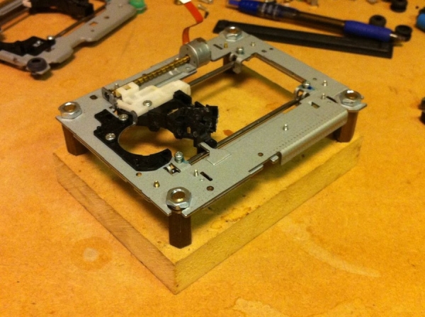
To make this as easy as possible I got hold of a piece of MDF just a little bit larger than the DVD-Rom stepper assembly. This will work as the base to hold both the X and Y axis. I found some spacers to hold the Y axis but bolts with a couple of nuts would work just as well. The measurements here are not critical but it is important that every axis is square to the other entire axis. I found that mounting the first assembly level with the MDF would make it easier to align everything.
The workspace is mounted on the old laser diode assembly. Make sure it is flat and level then glue something on that will serve as workspace. I found a piece of 1/4″ acrylic that worked out just fine. It made this workspace stable enough but as the laser can shine through it I was not sure if this would be a security hazard or not. Later I found the solution I think works out for the best. I cut a piece of the DVDR metal case to the same size as the acrylic and glued it on. This way it still very stable and you get a workspace that will be tough. One positive side effect is that you can secure whatever you are engraving with small magnets.
For the X axis I found some aluminum profiles in my junk bin but just about anything could be used as long as it is stable. Measure the height you feel will be right for what you want to engrave. I opted for 7.5″ long pieces for the support. This would give me a little under 2″ clearance.
One important thing, the mounting holes on the assembly are not symmetrical. Be sure to measure the distance from the bottom end of the supports to the linear guides. That way you will be sure to get everything aligned. Where you mount the X axis will be dependent on the laser mounting. The laser should be in the center of the work area when the Y axis is in the middle position. When you mount the axis to the base plate drill a small guide hole for the screws after you made sure that everything is square.
Now you should have the X and Y axis done and square to each other.
The laser mount does not have to be very sophisticated, mine is made from a small piece of plastic sheet and a clip then everything is glued together. Using a clip to hold the laser lets me change the focus point by simply slide the laser up and down. As with all other parts the size is not that important as long as everything is square. There are just one measurement you need to think about here, the laser should be in the center of the work area when the Y and X axis is in the center position.
Read more: Pocket Laser Engraver.