Summary of Plugduino – Arduino based 120 Volt outlet controller
This article details the "Plugduino," a DIY project enabling Arduino control of 120V home appliances. It combines an Arduino Uno with a relay shield to manage four independent outlets via sensors like potentiometers, motion detectors, or light sensors. The guide covers safety protocols for high-voltage work, schematic diagrams for power and control circuits, and a comprehensive parts list required to build the device for automation projects such as Halloween props or smart home lighting.
Parts used in the Plugduino:
- 1" x 1/4" fuse holder
- SPDT power switch
- Fast acting 7A 205V fuse
- 4 position dual row terminal block
- 16/3 120VAC extension cord
- 2 gang outlet wall plate
- 120VAC 15A duplex grounded outlets (2x)
- Dual gang outlet wall box extender
- Arduino Uno microcontroller
- SeedStudio Relay Shield V2.0
- 40mA 5mm white LEDs (4x)
- 40mA green LEDs (4x)
- 220 ohm 1/4 watt resistors (8x)
- 3-pole terminal blocks (4x)
- 36 pin single row pin header
- 120VAC to 12VDC 0.5A wall supply
- 10k ohm linear taper potentiometer
- Project enclosure
- Perforated project board
- LED holders and assorted hardware
- Shrink tubing and various gauge wires
give your Arduino a 120 volt kick in the pants!
The Arduino is a great tool for anyone interested in learning microcontroller programming, but after blinking some LEDs, what’s next? This project enables your Arduino to control real-world 120 Volt electrical appliances you have in your home.
what can you use a plugduino for?
Well, its great for Halloween prop controller to automate your lasers, fog machines, fans and such in an intelligent way. You can use beam breaks, contact pads, distance sensors, and so on to control up to 4 devices independently or in unison to make a unique experience.
But you can also use in the house to control appliances based on sensors such as temperature, humidity, motion, light, and so on to open curtains, turn on lights, fans based on environmental conditions. You can also use it for more whimsical thingslike sign marquees, animated Christmas light lights, super sized Simon game, and anything that takes input, runs program logic, and controls 120V devices.
plugduino is a smart relay controller
which means that you can write a program that determines how each of the four electrical outlets are turned on or off, and in addition supply up to 4 inputs into the logic to interface it to the outside world. As a simple example, you can make a sequencer for the lights with a speed control simply by connecting a potentiometer to one of the inputs and using its value to control the sequencing speed.
Step 1: Lets pop it open!
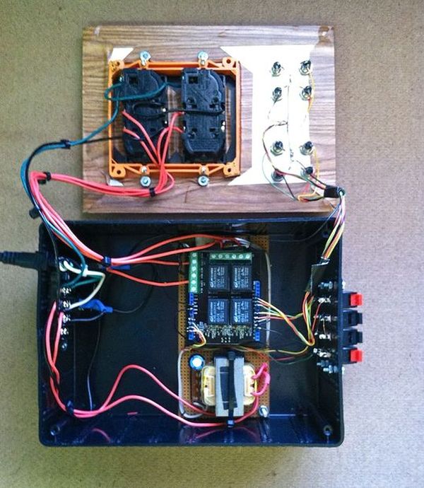
Inside the plugduino you’ll find just a few basic bits that are wired together to make the magic happen. The real mojo in the plugduino comes from the combination of an Arduino microcontroller and a SeedStudio V2.0 Relay Shield; the rest of the stuff is just wiring and connectors.
warning: working on 120V circuits can be dangerous and potentially lethal
make sure you know what you are doing and proceed carefully!
Because this project involves house wiring, follow the instructions carefully to ensure a safe build and always test and operate the device with a safety fuse. With the proper use of rated terminal strips, shrink tubing, wiring, and safety procedures, you can build this project safely, but always be aware that the risk of electrical shock is present!
The power circuit consists of a 3 prong power plug, fuse, terminal strip, and two dual outlets. The four red wires between each outlet and the control board provide the switching circuit. Note that this circuit is physically isolated from the rest of the wiring.
The control circuit consists of an Arduino Uno, a SeedStudio V2.0 relay shield, and a skinned 12V power wall wart. The program running on the Arduino reads sensor input and controls the status of the relays on the Relay Shield and hence the outlets. The control board is mounted onto a section of perfboard, and fastened to the bottom of the cabinet using nut/bolt/spacers.
The sensor input terminals support four sets of analog inputs to the Arduino to provide for switches, potentiometers, and the like. Depending on your needs, you could connect these terminals to whatever inputs ( analog and/or digital ) as you see fit. You could also use different connectors that might better suit your application, such as terminal posts, ribbon connector, etc.
The I/O status indicators display which outlets have power applied to them, and which inputs are generating an input value. The indicators are separated into two groups of input and output. In this project, white LEDs are used to display output status, and green LEDs are used to display input status.
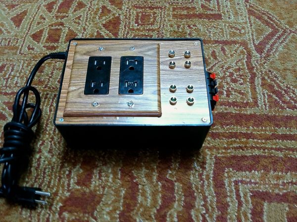
The cabinet is a standard plastic and aluminum project box with contact paper applied to the front panel for aesthetics.
Step 2: Parts list
Most of the items required for the plugduino can be found at RadioShack, online, and Home Depot. The links to the parts listed below are recommendations, but you can substitute as you wish. Note that some links refer to multiple parts in the package so check your inventory count carefully.
power circuit
control circuit
power supply
sensor test circuit
miscellaneous
Step 3: Power circuit schematic
the power circuit consists of a 120V 3 prong outlet cord, fuse housing and fuse, switch, terminal block, control circuit power supply, and duplex outlets. The interface between the power circuit and the control circuit is the job of the Relay Shield, which contains both high and low power connections.
The power circuit connects the 120V power plug to both the low voltage power supply ( via neutral and hot ), and to the outlets through the switches on the Relay Shield (via neutral ). The outlets share both ground and hot connections completing the circuit.
the fuse must be used in any house powered circuit even with the use of a grounded connection such as this. The fuse is used to protect from current overload primarily caused by the devices that are plugged into the outlets. We recommend using a 7A 250V fuse to stay well within the load limits of the relays on the shield.
the terminal block provides a clean connection between the input circuit and the high power circuitry in the cabinet. The idea is to minimize exposed contact to the supply. By using shrink tubing on all remaining connections the terminal block is the only point of contact between the mains supply and the device.
the power supply powers the Arduino and Relay Shield at 12 Volts DC. The power supply uses a transformer to create a separate isolated low voltage circuit. This low voltage circuit provides power for the microprocessor, the relay coils, the LEDs, and serves the reference circuit for sensor input.
the outlet block connects to the switch contacts on the Relay Shield ( rated at 10A @ 250V ) to the 120 volt power source. Using the recommended 7 amp fuse, the total load on all the outputs is 120V * 7A ~ 800 watts. This load should be sufficient for most lighting applications, but be careful to check power ratings when using power hungry devices such as fog machines and fans.
Step 4: Control circuit schematic
the control circuit consists of the sensor input connector, the Arduino, the status LEDs, and the low power side of the Relay Shield. The schematic shown here displays input / output / status for one channel since all 4 channels are wired identically. The pins used on the control circuit boards are 5V, GND(1), GND(2), A0, A1, A2, A3, D3, D4, D5, D6, D7, D9, D10, and D11. In addition to this, pins D0 and D1 are used to program the Arduino.
the sensor inputs are connected to the analog inputs on the Arduino board ( A0, A1, A2, A3 ). The input voltages on these pins are converted into a 10 bit integer value such that the range between 0V and 5V and translated into a value between 0 and 1023 respectively. The ideal connector thus contains 3 inputs per sensor ( 5V, GND, A ) resulting in 12 connection points.
the sensor status indicators provide a way to see the analog values that are being used on the front panel, which can be very useful in determining how the controller logic is working. We are using white LEDs here to provide that feedback. The program running on the Arduino simply reads the analog sensor values, and outputs those values to respective LEDs using the PWM output pins D3, D9, D10, and D11. The PWM output has 8 bit resolution and therefore has 1/4th the resolution of the actual input.
control status indicators indicate which relays (and hence which outlets) are energized and provide a look at how the controller logic is working and to help debug device operation. The pins D4, D5, D6, and D7 are connected between the Arduino and the Relay Shield (via header) to energize the relays; this part of the circuit simply taps those pins to light up the green LEDs.
For more detail: Plugduino – Arduino based 120 Volt outlet controller
- What can you use a Plugduino for?
You can use it to automate Halloween props like lasers and fog machines or control home appliances based on environmental sensors. - How many devices can the Plugduino control independently?
- Does the Plugduino support sensor inputs?
- What is the recommended fuse rating for the power circuit?
- Can you adjust the sequencing speed of lights using this project?
- What voltage does the power supply provide to the Arduino?
- Are the power and control circuits electrically isolated?
- What components are used to display output status?
The device allows you to control up to 4 electrical outlets independently or in unison.
Yes, it supports four sets of analog inputs to interface with switches, potentiometers, and other sensors.
A 7A 250V fast-acting fuse is recommended to stay within the load limits of the relays.
Yes, connecting a potentiometer to an input allows you to control the sequencing speed of lights.
The power supply converts 120VAC to 12VDC to power the Arduino and Relay Shield.
Yes, the power circuit is physically isolated from the rest of the wiring to ensure safety.
White LEDs are used to display which outlets have power applied to them.