With 2020 being the year of COVID, having a toddler that was stuck at home (especially during the winter) presented the need for, well, stuff to do. So, my wife and I decided to turn our basement into a play place for our little girl.
We started by designing and building an indoor slide with a 4ft x 4ft platform at the top. The great thing about this was the built-in “bunker” underneath the platform. We quickly found that our little girl treated this as her own little fort – and who could blame her.
But I wanted to make it fun for her down there, and give her some lights to play with at the same time. So, I took some NeoPixels I had laying around and decided it was time to pair them with some illuminated buttons of varying colors. The result was a fun, interactive colorful lighting system that she could play and experiment with.
Supplies
Components
- Breadboard-built Arduino
- I did all of my prove-out programming on a standard Arduino Uno, then transferred everything over to a breadboard Arduino once I was satisfied; this allowed for a more sturdy construction
- Illuminated, Momentary Push Buttons (I used the following Adafruit 16mm buttons, but larger arcade-style buttons would work great as well)
- Red – Adafruit Product ID 1439
- Blue – Adafruit Product ID 1477
- Green – Adafruit Product ID 1440
- Yellow – Adafruit Product ID 1441
- White – Adafruit Product ID 1479
- SPDT Toggle Switch
- Non-illuminated Momentary Push Button (I used one I had just laying around – nothing special here)
- AC-to-DC Power Supply (I used Digi-Key part number 62-1317-ND)
- Large plastic electronics enclosure (I used Amazon ASIN B08MCWN2ZG)
- Used to house the microcontroller and mount the buttons and was mounted at toddler-level
- Small plastic electronics enclosure (I used Amazon ASIN B08MCZ17HW)
- This one housed an adult-accessible reset button wired into the Arduino, pressed in case our toddler left the lights turned on
- NeoPixel RGB Strips
- These can be cut to length – just be sure to modify the program as needed!
- Molex Standard 0.062″ Connectors/Housings
- Cord grips & miscellaneous wires/cords
Tools
- Computer running Arduino IDE
- Soldering Iron
- Heat Gun with Heat Shrink Tubing
- Wire Stripper
- 3D Printer (or do what I did – have a friend print it for you!)
- Hot Glue Gun
- Measuring Tools
- Drill
- Rotary Cutter
Step 1: Designing & Building the Circuit
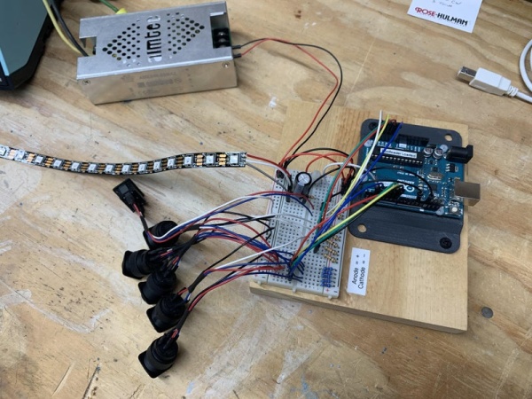
This project started with a standard Arduino Uno and a small breadboard. I love experimenting with NeoPixels, so I’m decently versed in connecting those; if you’re a bit more hesitant to work with them, I strongly encourage you to read through the Adafruit NeoPixel Überguide (https://learn.adafruit.com/adafruit-neopixel-uberguide).
To get things rolling, I knew I wanted to use 5 different colored buttons and a single toggle switch. The combination of these would determine what the NeoPixel strips were doing. The connections on my prototyping setup were all fairly easy; once I had them all working right, I made the wiring diagram, which I’ve attached here.
When working with NeoPixels, power consumption is always a factor. I knew I was going to be working with around 60 LEDs in the final install, so I needed to plan accordingly. Per the NeoPixel Überguide, a single pixel will consume 60mA when illuminated to maximum brightness white. You’ll see in my code that I do not have the brightness turned all the way up, but I did want to be on the safe side when it came to having enough power. In the end I opted for a 5vdc 5A power supply – and I’m glad I did, because I ended up adding additional pixels to my strip count…
Once hardware proveout was complete, I started to move everything over to a half-sized Perma-Proto solderable breadboard. I’ve used these in the past for longer-term projects, and I love how durable and easy to use they are. Mapping the wire leads on the Perma-Proto board was tedious, but very manageable given the wiring diagram I had paired with my ohmmeter.
I wanted to be sure that the enclosure lid was not going to be permanently attached to the breadboard, so I was hesitant to solder buttons directly to the Perma-Proto. I figured I’d give Molex connectors a try, which would allow me to connect and disconnect as needed. This was my first project working with Molex connectors, and there was a bit of a learning curve, but I ended up figuring them out.
Step 2: The Code – What Makes It Work
I’ll begin this section by saying that I am by no means an efficient coder. I pulled this code together using examples from the internet and help from forums. I would be very interested if anyone has better ways of executing this code.
The code file has descriptions of what each section does, so I’m not going to go into a huge amount of detail here. The general operation is fairly simple really – the code is looking for how many buttons are pressed at a time. The number of “pressed” buttons then determines which segment of code is being executed, and the combination of colored buttons determines what colors are illuminated on the NeoPixels via “case” programming.
My first instinct was to “add” the colors into a single RGB value for display on the stips, but after some internet searching I quickly realized that RGB values are not easily added. So I modified my program to alternate colors on the pixels. Basically if the user presses the BLUE button and the RED button, the pixels will alternate between blue and red. If the user adds, say, the GREEN button, the pixels will display a blue, red, green pattern. It proved to be an efficient compromise.
The code also illuminates the button LEDs to indicate which button(s) is(are) pressed at any time. It uses a debounce routine to ensure that the button isn’t inadvertently double pressed, and “latches” the button programmatically.
Finally, the code is monitoring the state of the toggle switch, and when it sees that state fall LOW (i.e. when the toggle is switched and the switch is between the two contacts), it throws the NeoPixels into a rainbow routine that lasts for a few seconds. This is just a fun little extra feature to play with.
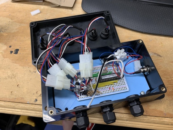
Step 3: Preparing the Enclosures
Since this project will be implemented in direct line of fire of a toddler, a sturdy housing is needed to ensure the circuitry stays intact and out of reach. The enclosures I bought on Amazon (see component list) worked great for this, but needed to be modified with mounting holes for buttons and cord grips. In the case of mounting my breadboard Arduino, I also needed to have a custom made backplate, so let’s look at that process first.
Measuring for the Backplate
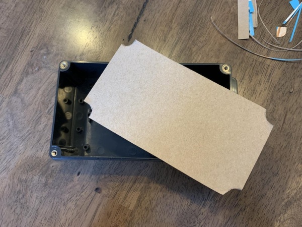
Because the Amazon seller did not supply dimensions for the holes molded into the back of the enclosure, I needed to get some decently accurate measurements of them. However, due to the depth of the box, I wasn’t able to get my calipers or a good tape measure to the holes. So I got creative.
I started by cutting a piece of cardboard that would slide down and cover all of the holes molded into the enclosure. This didn’t need to be very accurate, it just needed to sit on top of the mounting holes. Once that was made complete with a handle to help lower and raise it, I dabbed a little bit of fingernail polish on the mounting holes. While the nail polish was still wet, I lowered the cardboard and pressed it down, transferring the nail polish over to the cardboard. After that, I just needed to remove the cardboard and let the nail polish dry.
Once the nail polish was dry, it was easy to measure the hole pattern and transfer into a CAD software. I also took this opportunity to design in some standoffs for the breadboard Arduino to mount directly to the backplate. The attached .STL is designed for the larger enclosure I listed in my component list (Amazon ASIN B08MCWN2ZG) and has standoffs designed for an Adafruit half-size Perma-Proto breadboard (Adafruit p/n 1609). From there, I made my .STL and sent it over to a friend to have him print the backplate on his 3D printer.
Drilling for Buttons
Next task was to prepare the enclosure cover for the buttons and toggle switch. For this one, I used painters tape as a mask on the enclosure; this one made it very easy to mark the locations of the buttons. Once marked, it was as easy as drilling the appropriate size holes for the panel mount buttons. The rectangular hole for the toggle switch was cut using a rotary cutting tool, which unfortunately can be seen to have over cut in the corners.
Step 4: Bringing It All Together
With everything developed, tested, and proven on my workbench, it was time to bring everything together for final install.
My wife and I already knew how and where we wanted to mount everything, so I went in to this step with a game plan already. I used some scrap pieces of lumber for brackets to help mount enclosures to the structure, then tacked the NeoPixel strips up using plastic cable staples.
Once the wires were run to the controller, I made my final connections and gave it a shot – and it worked great!
Source: PlayPlace Lighting Using NeoPixels