I have been wanting to build a Geiger counter for a long time to complement my Peltier Cooled Cloud Chamber. There is (hopefully) not really much useful purpose in owning a Geiger counter but I just love the old Russian tubes and thought it would be great fun to build one. Then I came across the neat instructable by How-ToDo and thought about rebuilding it with some improvements (e.g. larger tube). After I got all the electronics and wired them it was time to design a suitable enclosure. When I showed the counter to a friend he said that I should make the enclosure look like the PKE meter from the 1980s ghostbuster movies. It did not take long to convince me that this was a great idea which would make it stand out from other Geiger counter builds.
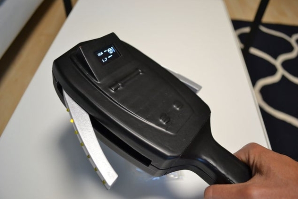
As you can see in the video the counter reacts to radioactivity with audible clicks from a piezo buzzer. In addition, the wings fold out when the count rate increases and the LEDs will blink faster. It also has a display showing the count rate and calculated radiation dose.
Supplies:
The project was build using the following components
- SBM-20 Geiger tube (e.g. ebay.de)
You can buy many old Geiger tubes from post soviet countries like Romania and Ukraine. At first, I bought a large SBM-19 tube which even came in the original packaging as shown on the picture above. For the final build I needed a smaller tube though so I bought an SBM-20 which came wrapped in Ukrainian newspaper and included a discount coupon for a Chernobyl tour 😉
- OLED display, 0.96″, 128×64 (e.g. ebay.de)
The picture shows a larger 1.8″ LCD display which I plan to use for another project
- Arduino Nano (e.g. ebay.de)
- Passive piezo buzzer (e.g. ebay.de)
- Step up module 5 – 12 V to 300 – 1200 V (e.g. ebay.de)
This generates the 400 V necessary to operate the Geiger tube
- Step up module 0.9 – 5 V to 5 V (e.g. ebay.de)
Since current drawn from the tube is negligible the module needs only be able to provide ~100 mA for the Arduino and display.
- LiPo/Li ion charger module (e.g. ebay.de)
Make sure to get the one with discharge protection that have separate ‘B+/-‘ and ‘Out+/-‘ pins
- 18650 Li ion battery (e.g. ebay.de)
I prefer the branded ones like LG since I do not trust a battery whose name contains the word ‘fire’.
These are for holding the tube so you do not have to solder it directly
- 10 KOhm resistor (e.g. conrad.de)
- 5-10 MOhm resistor (e.g. conrad.de)
- 470 pF capacitor (e.g. conrad.de)
- 2N3904 NPN transistor (e.g. conrad.de)
- slide switch (e.g. amazon.de)
- SG90 micro servo (e.g. ebay.de)
- 14 pcs of 3mm LEDs, yellow (e.g. conrad.de)
- 6 pcs M2.2×6.5 self tapping screw (e.g. conrad.de)
In addition, I used black and silver acrylic paint for the housing. Also epoxy and primer for smoothing the 3D print. As for every decent project you will also need lots of hot glue, some wire and a soldering iron.
Step 1: 3D Printed Parts
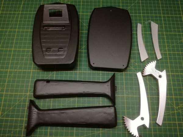
At first I wanted to use the PKE meter design by hobbyman but in the end it was easier to just make my own CAD model from scratch, although I copied hobbyman’s mechanism for moving the wings. The model was designed from pictures of the PKE meter toy by Mattel and you can find the stl files attached. After 3D printing I coated the parts with epoxy to smoothen the surface. In addition, the grip and housing body where glued together using epoxy filler. After epoxy coating the parts were sanded then sprayed with primer and painted in black and silver. Unfortunately, I did not manage to get a completely smooth surface, especially the top part of the housing body still has some visible layers.
Step 2: Servo Calibration
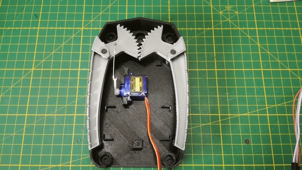
The goal of the next step was to find out the correct start and stop positions of the servo. The servo was attached to the housing and connected to one of the arms using a piece of wire salvaged from a paper clip. The servo was then connected to the arduino and the sweep example from the arduino servo library was used to determine the minimum and maximum position of the servo.
Step 3: Preparing LED Strips
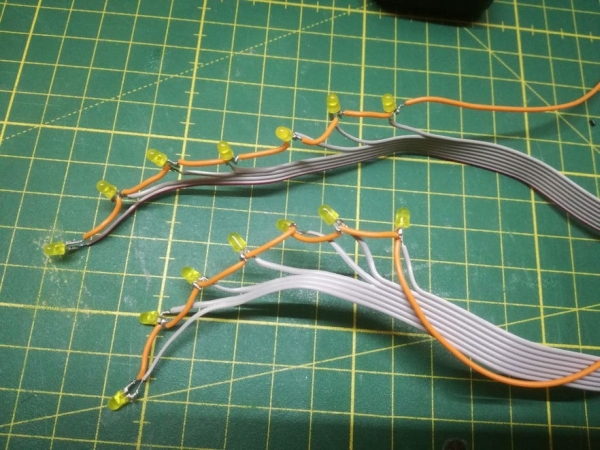
Next, I prepared two stripes of LEDs with seven LEDs each. The cathodes were all connected to the same wire while each LED anode was soldered to the individual wire of a ribbon cable. Later the anode wires of each LED for both wings will be connected so that the LEDs always light up together. The LEDs were then attached to the wings using hot glue.
Step 4: Wiring Electronics
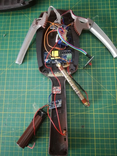
Finally, I wired all of the electronics according to the attached schematics which was basically copied from the Arduino Geiger Counter by How-ToDo. All wires were directly soldered to the arduino terminals so that it fits below the wings, only at the OLED display and input of the HV module I used Dupont connectors. Before connecting the output of the HV module it should be set to 400 V using a multimeter. (Be careful when handling high voltages!) As already mentioned the Geiger tube was connected with the help of fuse clips. The transistor, capacitor and 10 kOhm resistor were soldered onto a small piece of breadboard. Another piece of breadboard was used for the common ground and 5 V connections. You may have noticed that I did not use any current limiting resistors for the LEDs. While this is certainly not good practice, most LEDs seem to be able to handle a forward voltage of 5 V but it may reduce their lifetime.
In the end I had to disconnect the wire sensing the battery voltage (input A3 on arduino) because it did somehow power the arduino even if the slide switch was turned off. I am not sure if this was due to a short or ‘normal’ behaviour of the circuit.
Step 5: Uploading Code and Testing
Before uploading the code to the arduino, the min and max positions of the servo that were determined earlier have to be entered. The code uses interrupts to detect a geiger pulse and clicks the piezo buzzer. It also sums up the counts over an intergation time of 1 sec and then calculates the running average over 5 measurements. From this the count rate in cpm is calculated and converted to a radiation dose in µSv/h according to the conversion factor from this website. For a higher count rate the LEDs will blink faster and the wings will fold out. Also, the count rate and radiation dose as well as the current battery voltage are shown on the display.
I tested the circuit using a small piece of pitchblende (uranium oxide) which I also used in my Cloud Chamber project.
Read more: PKE Meter Geiger Counter