Pyroelectric (“Passive”) InfraRed sensors:
PIR sensors allow you to sense motion, almost always used to detect whether a human has moved in or out of the sensors range. They are small, inexpensive, low-power, easy to use and don’t wear out. For that reason they are commonly found in appliances and gadgets used in homes or businesses. They are often referred to as PIR, “Passive Infrared”, “Pyroelectric”, or “IR motion” sensors.
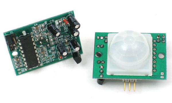
PIRs are basically made of a pyroelectric sensor (which you can see above as the round metal can with a rectangular crystal in the center), which can detect levels of infrared radiation. Everything emits some low level radiation, and the hotter something is, the more radiation is emitted. The sensor in a motion detector is actually split in two halves. The reason for that is that we are looking to detect motion (change) not average IR levels. The two halves are wired up so that they cancel each other out. If one half sees more or less IR radiation than the other, the output will swing high or low.
Along with the pyroelectic sensor is a bunch of supporting circuitry, resistors and capacitors. It seems that most small hobbyist sensors use the BISS0001 (“Micro Power PIR Motion Detector IC”), undoubtedly a very inexpensive chip. This chip takes the output of the sensor and does some minor processing on it to emit a digital output pulse from the analog sensor.
For many basic projects or products that need to detect when a person has left or entered the area, or has approached, PIR sensors are great. They are low power and low cost, pretty rugged, have a wide lens range, and are easy to interface with. Note that PIRs won’t tell you how many people are around or how close they are to the sensor, the lens is often fixed to a certain sweep and distance (although it can be hacked somewhere) and they are also sometimes set off by house pets. Experimentation is key!
Some basic stats
These stats are for the PIR sensor in the Adafruit shop which is very much like the Parallax one. Nearly all PIRs will have slightly different specifications, although they all pretty much work the same. If there’s a datasheet, you’ll want to refer to it
- Size: Rectangular
- Price: $10.00 at the Adafruit shop
- Output: Digital pulse high (3V) when triggered (motion detected) digital low when idle (no motion detected). Pulse lengths are determined by resistors and capacitors on the PCB and differ from sensor to sensor.
- Sensitivity range: up to 20 feet (6 meters) 110 degrees x 70 degrees detection range
- Power supply: 3.3V – 5V input voltage,
- BIS0001 Datasheet (the decoder chip used)
- RE200B datasheet (most likely the PIR sensing element used)
- NL11NH datasheet (equivalent lens used)
- Parallax Datasheet on their version of the sensor
More links!
Step 1: How does it work?
PIR sensors are more complicated than many of the other sensors explained in these tutorials (like photocells, FSRs and tilt switches) because there are multiple variables that affect the sensors input and output. To begin explaining how a basic sensor works, we’ll use the rather nice diagram below (if anyone knows where it originates plz let me know).
The PIR sensor itself has two slots in it, each slot is made of a special material that is sensitive to IR. The lens used here is not really doing much and so we see that the two slots can ‘see’ out past some distance (basically the sensitivity of the sensor). When the sensor is idle, both slots detect the same amount of IR, the ambient amount radiated from the room or walls or outdoors. When a warm body like a human or animal passes by, it first intercepts one half of the PIR sensor, which causes a positive differential change between the two halves. When the warm body leaves the sensing area, the reverse happens, whereby the sensor generates a negative differential change. These change pulses are what is detected.
The PIR sensor itself
The IR sensor itself is housed in a hermetically sealed metal can to improve noise/temperature/humidity immunity. There is a window made of IR-transmissive material (typically coated silicon since that is very easy to come by) that protects the sensing element. Behind the window are the two balanced sensors.
Check out the images for more details:
Step 2: Lenses
PIR sensors are rather generic and for the most part vary only in price and sensitivity. Most of the real magic happens with the optics. This is a pretty good idea for manufacturing: the PIR sensor and circuitry is fixed and costs a few dollars. The lens costs only a few cents and can change the breadth, range, sensing pattern, very easily.
In the diagram above, the lens is just a piece of plastic, but that means that the detection area is just two rectangles. Usually we’d like to have a detection area that is much larger. To do that, we use a simple lens such as those found in a camera: they condenses a large area (such as a landscape) into a small one (on film or a CCD sensor). For reasons that will be apparent soon, we would like to make the PIR lenses small and thin and moldable from cheap plastic, even though it may add distortion. For this reason the sensors are actually Fresnel lenses (see image below).
OK, so now we have a much larger range. However, remember that we actually have two sensors, and more importantly we dont want two really big sensing-area rectangles, but rather a scattering of multiple small areas. So what we do is split up the lens into multiple section, each section of which is a fresnel lens.
The different faceting and sub-lenses create a range of detection areas, interleaved with each other. That’s why the lens centers in the facets above are ‘inconsistent’ – every other one points to a different half of the PIR sensing element
Step 3: Connecting to your PIR
Most PIR modules have a 3-pin connection at the side or bottom. The pinout may vary between modules so triple-check the pinout! It’s often silkscreened on right next to the connection. One pin will be ground, another will be signal and the final one will be power. Power is usually 3-5VDC input but may be as high as 12V. Sometimes larger modules don’t have direct output and instead just operate a relay in which case there is ground, power and the two switch connections.
The output of some relays may be ‘open collector’ – that means it requires a pullup resistor. If you’re not getting a variable output be sure to try attaching a 10K pullup between the signal and power pins.
An easy way of prototyping with PIR sensors is to connect it to a breadboard since the connection port is 0.1″ spacing. Some PIRs come with header on them already, the ones from Adafruit don’t as usually the header is useless to plug into a breadboard.
By soldering in 0.1″ right angle header, a PIR is easily installed into a breadboard!
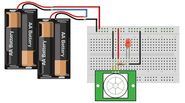
Step 4: Testing your PIR
Once you have your PIR wired up its a good idea to do a simple test to verify that it works the way you expect. This test is also good for range testing. Simply connect 3-4 alkaline batteries (make sure you have more than 3.5VDC out but less than 6V by checking with your multimeter!) and connect ground to the – pin on your PIR. Power goes to the + pin. Then connect a basic red LED (red LEDs have lower forward voltages than green or blue so they work better with only the 3.3v output) and a 220 ohm resistor (any value from 100 ohm to 1.0K ohm will do fine) to the out pin as shown. Of course, the LED and resistor can swap locations as long as the LED is oriented connection and connects between out and ground
For more detail: PIR Motion Sensor Tutorial