Overview
As the name suggests, PID algorithm consists of three basic coefficients; proportional, integral and derivative which are varied to get optimal response. Closed loop systems, the theory of classical PID and the effects of tuning a closed loop control system are discussed in this paper. The PID toolset in LabVIEW and the ease of use of these VIs is also discussed.
1. Control System
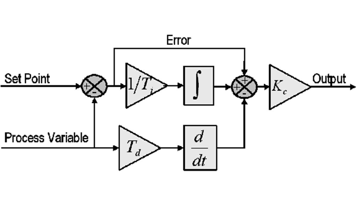
The basic idea behind a PID controller is to read a sensor, then compute the desired actuator output by calculating proportional, integral, and derivative responses and summing those three components to compute the output. Before we start to define the parameters of a PID controller, we shall see what a closed loop system is and some of the terminologies associated with it.

Closed Loop System
In a typical control system, the process variable is the system parameter that needs to be controlled, such as temperature (ºC), pressure (psi), or flow rate (liters/minute). A sensor is used to measure the process variable and provide feedback to the control system. The set point is the desired or command value for the process variable, such as 100 degrees Celsius in the case of a temperature control system. At any given moment, the difference between the process variable and the set point is used by the control system algorithm (compensator), to determine the desired actuator output to drive the system (plant). For instance, if the measured temperature process variable is 100 ºC and the desired temperature set point is 120 ºC, then the actuator output specified by the control algorithm might be to drive a heater. Driving an actuator to turn on a heater causes the system to become warmer, and results in an increase in the temperature process variable. This is called a closed loop control system, because the process of reading sensors to provide constant feedback and calculating the desired actuator output is repeated continuously and at a fixed loop rate as illustrated in figure 1.
In many cases, the actuator output is not the only signal that has an effect on the system. For instance, in a temperature chamber there might be a source of cool air that sometimes blows into the chamber and disturbs the temperature.Such a term is referred to as disturbance. We usually try to design the control system to minimize the effect of disturbances on the process variable.
For more Details: PID Theory Explained
