Summary of Piano Metronome
This article details a DIY Arduino-based piano metronome featuring customizable light and sound tempos, a digital display, and real-time clock functionality. The project utilizes an Arduino Uno R3, a rotary encoder for menu navigation, an LCD screen, and RGB LEDs to create a portable device housed in a custom case. While the current version includes basic timing and volume control, future iterations plan to integrate USB charging via 18650 batteries.
Parts used in the Piano Metronome:
- Arduino UNO R3 card and DC Plug
- DS1302 Real Time Clock plus 2032 button battery
- Two pole switch, coloured wires, PCB female plugs, heatshrink, PCB board, 3mm plastic supports
- LED plus 330ohm resistor
- PAM8403 Digital Amplifier 3W
- Digital Rotary Encoder with central push button
- 8 Ohm 1W speaker
- 20 X 4 line LCD screen using IC2 communications
- 50x90x150mm project box
- 4 x Neopixel RGB common anode LEDs
- 2 x Adjustment push on control knobs
- 2 x 18650 batteries and twin battery holder
- Blank PCB board
- M3 20mm board supports and 5mm screws
This project was conceived of after I examined the types and styles of various off-the-shelf Metronomes. I am currently learning to play the piano and having a Metronome in order to keep time was necessary. I felt sure that I could build one based on a standard Arduino Uno R3 board. The resultant Metronome has a combined light and sound feature which can be customized to reflect the tempo of the beat. While V1 of the project is complete a V2 is being considered based on some new features such as adding a 18650 Battery shield to allow charging of the batteries via a USB charging cable. I added a simple time display feature in this version, however a future version could include the time in providing a fixed number of beats option.
Supplies
1. Arduino UNO R3 card and DC Plug, terminal type
2. DS1302 Real Time Clock plus 2032 button battery
3. Two pole switch, coloured wires, PCB female plugs, heatshrink, PCB board, 3mm plastic supports
4. LED plus 330ohm resistor
5. PAM8403 Digital Amplifer 3W
6. Digital Rotary Encoder with central push button
7. 8 Ohm 1W speaker
8. 20 X 4 line LCD screen using IC2 communications
9. 50x90x150mm project box
10. 4 x Neopixel RGB common anode LEDs
11. 2 x Adjustment push on control knobs.
12. 2 * 18650 batteries and twin battery holder
13. two pole switch.
14. a quantity of plastic M3 20mm board supports and 5mm screws
15. Blank PCB board, 20mm x 50mm approx.
Step 1: CONSTRUCTION
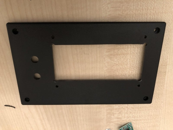
I freely accept that getting all of the above components into a 50x90x150mm project box is not easy and a larger project would have made things easier. However as the completed project shows it is possible. While I have not shown it, I recommend constructing the circuit on a suitable breadboard and testing its operation with the downloaded software. Construction starts with four equally spaced 8mm holes drilled into the top of the project box, to allow the four LED lights to be located there. Additionally, two 5mm holes are drilled on the face plate for the rotary encoder and Amp Volume control, a single 5mm hole is drilled in the center of project box’s side to allow access to the speaker, finally a single 12mm hole is drilled on the side of the project box to allow the Off/On circular two-pole switch to be installed.
Using a jigsaw and file a 96mm by 40mm square opening is made in the front panel to allow the 4×20 display to be inserted into the opening. It will also be necessary to drill 10 * 3mm holes in the front (4) and back panels (6) of the project box to allow for the M3 screws. The Arduino UNO R3 is wired to its components as laid out in the attached Fritzing circuit diagram.
The faceplate logo print, see attached PDF, is printed cut to shape and attached to the front panel of the project box. The IC2 controller is soldered to the 20×4 LCD screen and this screen is then attached to the front panel, after being inserted into the square cutout and fastened using 4 x M3 screws.
The two-pole switch is inserted through the 12mm hole on the side of the project box and the 8W speaker is glued to the inside of the project box so that the middle of the speaker is directly opposite the 5mm hole on the project box’s side panel. The rotary encoder and Amp volume control are attached to the inside of the project box’s lid and both of the knob control bars are past through the face plate so that they finish in the correct position in the center of the logo printout. Finally, the two control knobs are pushed onto the control bars.
When soldering the twin 18650 battery holder, ensure that the batteries are in series so that a total voltage of 7.2V is supplied, via the DC plug, to the Arduino. The 4 RGB LED light array is constructed using a blank PCB board, as per the Fritzing diagram. Where possible connections between components should be soldered, however if Dupont wires are used then it is recommended that all are glued in place after being tested.
Step 2: OPERATION
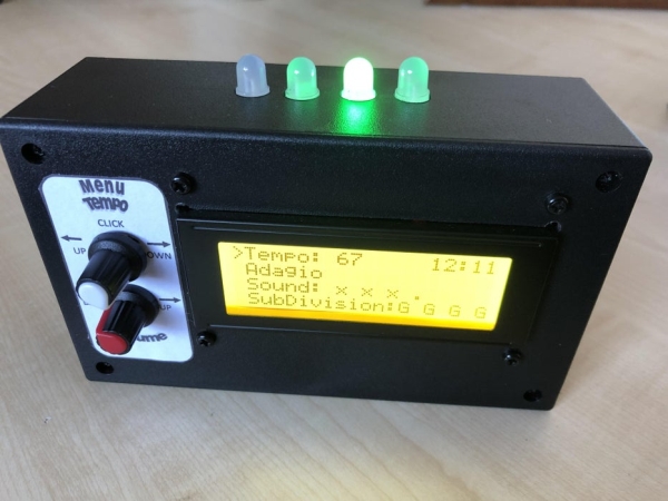
The Volume control increased the sound level if turned to the left, and decreased the sound level if turned to the right. The Menu/Tempo control initially starts in the Tempo option and turning it to the left will Increase the tempo while turning it to the right will reduce the Tempo. By clicking this same control, at the end of the light sequence, the menu options can be cycled through: Tempo, Sound formats, Light formats, Adjust clock Hours, and Adjust clock Minutes. If the unit is switched off the default Tempo (67), Sound (x,x,x.), and Light (G,G,G,G) formats will be restored.
Step 3: SOFTWARE
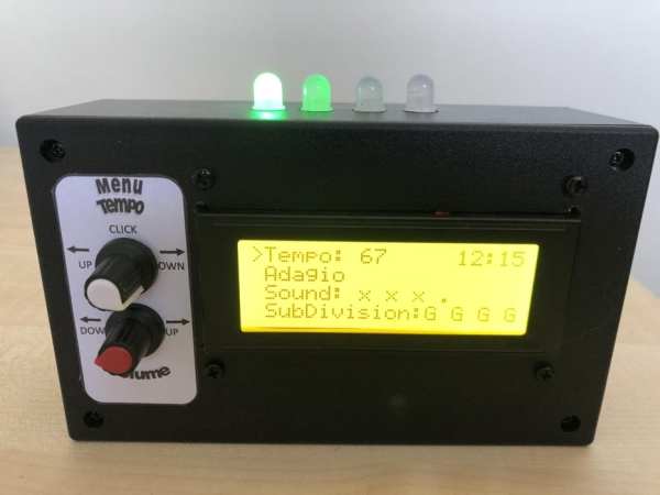
Version 3.1 of the software allows the user to adjust the Tempo from 20 to 250 beats per minute, at the same time the screen will display the description of this tempo, for example the range 41 to 60 beats per minute will display “Largo”. There are nine different sound formats including silent, with two different sounds, a short beep or a longer beep. In addition, there are nine different light formats including off, with two different lights available to select either red or green. The final two menu options are for setting the clock time, using the control, the values of the hours and minutes can be adjusted. A range of 0 to 59 for minutes and 0 to 23 for hours.
The following Arduino Library files are required:
#include (stdint.h)
#include (SPI.h)
#include (OneButton.h)
#include (Rotary.h)
#include (Wire.h)
#include (LiquidCrystal_I2C.h)
#include (Adafruit_NeoPixel.h)
#include (DS1302.h)
All of the above files can be found on the www.github.com web site. The software was compiled against the Arduino Uno board and used Ardunio IDE version 1.8.13
Source: Piano Metronome
- How can I adjust the tempo on this metronome?
Turn the Menu/Tempo control to the left to increase the tempo or to the right to reduce it. - What is the range of beats per minute available?
The software allows adjusting the tempo from 20 to 250 beats per minute. - Can I change the light format on the device?
Yes, there are nine different light formats including off, red, or green options accessible via the menu. - Does the device include a real-time clock feature?
Yes, the project uses a DS1302 Real Time Clock to allow adjustment of hours and minutes. - How do I cycle through the menu options?
Click the rotary encoder control at the end of the light sequence to cycle through Tempo, Sound formats, Light formats, and clock settings. - What happens if the unit is switched off?
The default Tempo (67), Sound (x,x,x.), and Light (G,G,G,G) formats will be restored upon restarting. - How should the 18650 batteries be connected?
The twin 18650 battery holder must be soldered so the batteries are in series to supply a total voltage of 7.2V. - Which Arduino IDE version was used for this project?
The software was compiled using Arduino IDE version 1.8.13 against the Arduino Uno board.