Since when white light emitting high brightness LED are available, the handover from traditional lighting bulbs to the solid-state lighting has become irreversible: LEDs have an efficiency (expressed in lumens/watt) higher than that of almost all the traditional lamps (except, at the moment, the large sodium vapor lamps used for street lighting, unusable in closed environments for the high power required and the chromatic aberration they produce) at a cost that is today less prohibitive than it was a few year ago. They are indeed very sturdy and have a very acceptable ratio of luminous flux and size.
In common with the traditional lamps, at least with fluorescent and neon, white LEDs have the characteristic to be produced to emit, depending on the model, a shade of white that ranges from warm (3,000 K) to cold (over 6,000 K). For this reason, when you want to create a lighting solution with light emitting diodes, you must be careful about what you purchase, if you just take the first lamp you can end up having a lighting that is not exactly what you want.
Another problem arises if you want to achieve lighting that can change the shade of the white according to the taste or mood of the moment, or even just to suit the needs of the guests; in this case you need a system which allows to vary the shade of the light emitted. Each LED, however, is made to give a certain color temperature and cannot be changed. Anyway there is a solution: use diodes both in warm and cold white, mixing the light in varying proportions.
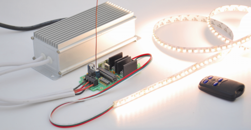
This is what the system described in this article does: basically a controller for two groups of white LEDs or for strips consisting of warm and cold white LEDs, driven separately (we tried with this solution) in PWM mode, so to vary the individual luminous flux of the two components and obtain a light that is a mixture of warm and cold white, with the chosen shade.
The system consists of a control circuit for LED strips with remote control receiver, remotely controlled by a radio signal in the UHF band at 433.92 MHz using a standard TX; the transmitter is amplitude-modulated with four channels; with the buttons on the transmitter you can manage the channels individually: raise and lower the brightness of the different rows of LEDs with warm and cold light.
Since the transmitter is a standard commercial model based on the UMC UM3750 IC (an evolution of the classic MM53200 with 4.096 combinations with binary 12-bit encoding) we won’t describe it; we will focus, instead, on the receiver/controller of which we will publish and describe the circuit diagram in the next paragraphs.
Receiver diagram
The controller is a combination of a hybrid Aurel AC-RX2 receiver tuned on 433.92 MHz and a PIC16F876A microcontroller programmed to act as the decoder of the code of the button pressed on the remote control. It generates two independent PWM signals and controls with them the gates of two enhancement-mode MOSFET with N-channel, which must drive the two LED strips or, more generally, groups of white LEDs. Since the transistors are configured in common-source, the circuit is suitable to drive common anode LED strips: we’ll in fact make available on the appropriate terminal the positive power supply and the MOSFET drain so that the circuit can drive the diodes bringing the cathodes to ground, with the times and manner prescribed by the PWM.
Let’s take a look at the circuit diagram: after the power-on, the Microchip microcontroller initializes its I/O and sets RC3 as input without pull-up dedicated to capture the data coming from the radio receiver U2, while. always as inputs, but with internal pull-up, sets RB2, RB3, RB4, RB5, RB6, RB7, which will be used to read the dip-switch DS1; instead RB0 is set as the output for the command of the signaling LED during procedures and RC1 and RC2 are set as the output of the PWM signal that drives the gate of the MOSFET T1 and T2.
Before proceeding, it is better specify that the output OUT1 (i.e. T1) controls the cold light LED (cold white) while OUT2 acts on the warm light ones (Warm white).
The wireless U2 receiver module is an AC-RX2 Aurel equipped with antenna signal amplifier (which gives a sensitivity of -106 dB),a superregenerative tuning stage tuned at 433.92 MHz using calibrated compensator at the factory and equipped with RF filter and amplitude demodulator; completes the module equipment, a squaring with a digital signal comparator (TTL level) coming from pin 14 and an LF amplifier of the output signal from the AM demodulator.
When pressing one of the buttons on the transmitter, the radiated RF signal reaches the receiving antenna of the module AC-RX2, which demodulates the data component and sends it to the pin 14; hence, the microcontroller takes the TTL pulse, places them in RAM and analyzes them with an appropriate firmware routine that, first of all, discerns among many signals picked up from the ether, the one that is compatible with the format of the UM3750 encoding. If so, checks if the code is one of those stored during the self-learning procedure and, if not, deletes the data from the RAM and gets ready for a new analysis.
For more detail: The perfect Remote, Programmable, Controller for interactive LED strips