Do you edit?
Do you design?
Do you Game?
Do you use a computer?
Well the PC Palette perfectly fits your needs, be it editing, be it designing, be it gaming or even just using a computer this accessory can help you do your work efficiently.
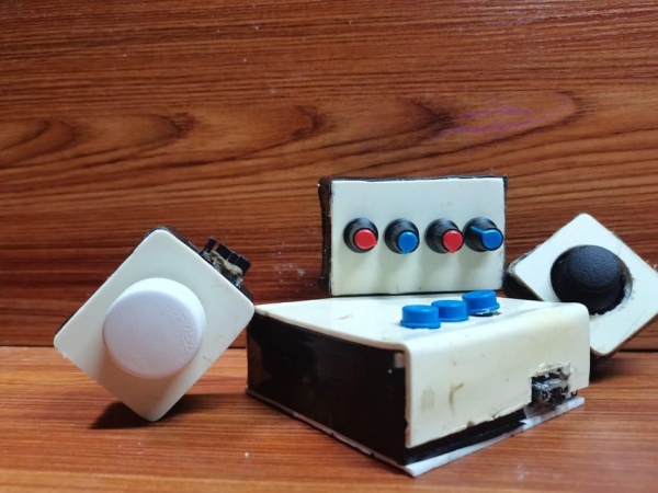
Sure there are many of these in the market but they are not customizable, they don’t exactly suit your needs and they are very expensive. So here is a alternative that you can make for a fraction of the price and it is completetly customizable, portable and efficient.
Step 1: Gather Your Supplies
An Arduino Pro Micro
A joystick module
A Rotary Encoder
Four Potentiometers
Four Push buttons
Some Wires (jumper wires and regular circuit wires)
Note : This project can be easily customized so feel free to add extra components but the Arduino Pro Micro has limited pins so you will have to look up on that
Step 2: The Design
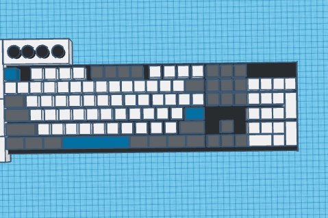
After you have gathered all of your components it’s time to start designing the PC palette. After a lot of thinking I came up with a efficient design that can fit around your keyboard, the components can be removed so that it is portable.
To make you understand better I have divided it into 4 parts taking you through all of the 4 units
The macro keypad (the brains of the PC Palette)
The joystick Module
The rotary Encoder
The volume controller
Step 3: Lets Start With the Joystick
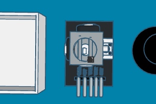
The joystick is actually a really useful add on that you will be using a lot and it is really easy to make.
For this unit you will need –
A joystick
A box to put in into
Optional –
A non-locking push button (You will need this to activate the joystick mouse but I used the button that is integrated in the joystick itself)
Some wires (including a male jumper wire)
Okay, now follow the pictorial above.
Step 4: The Rotary Encoder
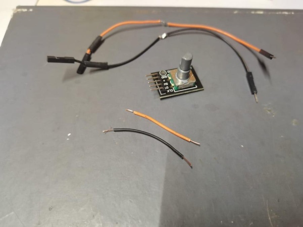
This is a crucial device especially when you edit in programs like premier pro, Da Vinci Resolve, etc. This device can be used as a jog wheel or a media controller.
For this unit you will need –
a rotary encoder
An enclosure
some jumper wires(Female to male and male to male)
A knob
This one is a bit complicating so I will write down the steps
Gather Your materials
solder a regular circuit wire to the ground (GND) and the Positive (+) pins on the encoder
next, connect the other end of the circuit wire to the center of the female to male jumper wires
now insulate the exposed parts and paste the ends of the jumper wires
the following steps should not be followed if the entire project is being done in one box
take three female to male jumper cables and put the female end of it and stick it out (by cutting a small slit ) in the opposite side of the enclosure
now take the female end of the two power cables and stick it out of the enclosure as well(on the same side as the three other cables)
make sure that the negative (GND) and the positive (+) connect to the same pins as written on the joystick
cut a slit in the opposite side of the enclosure and stick out the three remaining encoder pins (you can cut off the positive (+) and negative (GND) pins on the encoder
stick out the male side of the joystick cables in the same side as the rotary encoder pins
Ok your done!
Step 5: Volume Control Unit
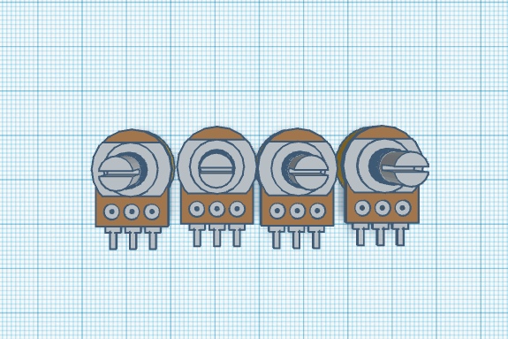
This is a very handy unit to very quickly adjust your computer volume. This unit uses deej to control your computers volume It is just like the windows volume mixer but physical!
For this unit you will need –
4 Potentiometers (You can use any amount)
4 knobs
An enclosure
Some wires (regular circuit wires and male to male jumper wires)
Start off by pasting all of your potentiometers in a row
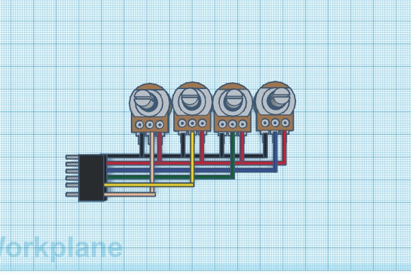
Now connect them as shown in the above picture (You can cut the male to male jumper wires in half and use them as the output pins)
next put in into the enclosure and cut a slit in the side where the jumper wires come out
drill holes on the top of the enclosure
and put it all together
and done!
Step 6: The Macro Keypad
This is the brains of the whole system. It contains three macro buttons that can come in handy for keyboard shortcuts. The shortcuts are completely customizable and more buttons can be added as well.
For this unit you will need –
A Arduino Pro Micro
Male to male Jumper wires
3 tactile push buttons (You can use keyboard switches as well)
3 Caps for the buttons
A PCB board
Ok that’s it now let’s get building,
First and foremost I strongly recommend you to prototype this on a breadboard (upload the code and test your components thoroughly) , I was having trouble with fritzing so i have written the connections below (will be updating once I resolve the fritzing issue 🙂 )
Connect the CLK pin on the rotary encoder to the 15 pin
connect the DT pin on the rotary encoder to the A2 pin
Connect the SW pin on the rotary encoder to the A3 pin
Connect the VRX pin on the joystick to the A0 pin
Connect the VRY pin on the joystick to the A1 pin
connect the SW pin on the joystick to the 6 pin
* connect the joystick and the rotary encoders power wires together
Connect the first potentiometer to the 4 pin
Connect the second potentiometer to the 8pin
Connect the third Potentiometer to the 9 pin
Connect the last potentiometer to the 10pin
*connect the positive and negative pins of the potentiometer to the VCC and GND pins on the Arduino
Connect the first button to the 2 pin
Connect the second button to the 3 pin
Connect the last button to the 5 pin
*connect one pin from all the buttons to ground (GND)
Once you get it prototyped start by soldering the Arduino into a PCB board
next wire it all up (You might have to cut the female to female jumper wires in half and use them to make the input pins for the joystick, rotary encoder and volume control units)
note – make sure to connect female jumper wires to the joystick, rotary encoder and volume control inputs unless you are doing the entire project in one box
cut slits in the enclosure for the female sides of the joystick, rotary encoder and volume control units as show in the 3d diagram above.
Put the buttons and the Arduino in place and close the enclosure.
Step 7: Code
////Developed By Abdurrahman Sameer////
//////Youtube  Abdurrahman Sameer//////
//Website  abdurrahmansameer.github.io//

//PC Palette//

#include <Mouse.h>
#include "Keyboard.h"

// include a EEPROM library for memorizing last function
#include <EEPROM.h>


#define  OUTPUT_B 15


#define  OUTPUT_A A2


#define  BUTTON A3
#define EDITING_MODE 5
#define ZOOM_MODE 7

#define BUTTON_A 2
#define BUTTON_B 3
#define BUTTON_C 4


bool aState;


bool aLastState;


bool lastButtonState = 0;

const int numMode = 2;


const int switchPin = 6;

const int xAxis = A0;         // joystick X axis
const int yAxis = A1;         // joystick Y axis
int range = 12;
int responseDelay = 5;
int threshold = range / 4;
int center = range / 2;

bool mouseIsActive = false;
int lastSwitchState = LOW;

void setup() {

  Keyboard.begin();


  pinMode(OUTPUT_A, INPUT);


  pinMode(OUTPUT_B, INPUT);


  pinMode(BUTTON, INPUT_PULLUP);
  pinMode(EDITING_MODE, INPUT_PULLUP);
  pinMode(ZOOM_MODE, INPUT_PULLUP);
  pinMode(BUTTON_A, INPUT_PULLUP);
  pinMode(BUTTON_B, INPUT_PULLUP);
  pinMode(BUTTON_C, INPUT_PULLUP);

  aLastState = digitalRead(OUTPUT_A);

    pinMode(switchPin, INPUT);
  pinMode(ledPin, OUTPUT);

  Mouse.begin();
}


long lastClickTime = 0;
long tempCount = 0;

void loop() {

      if (digitalRead(BUTTON_A) == LOW)
    {
         Keyboard.press(KEY_RIGHT_CTRL);
          Keyboard.press('c');
                }
    if (digitalRead(BUTTON_A) == HIGH)
    {
     Keyboard.releaseAll();

    }
    if (digitalRead(BUTTON_B) == LOW)
    {
      Keyboard.write((char) 0x87);
      Keyboard.press(42);          //print screen

    }
    if (digitalRead(BUTTON_B) == HIGH)
    {
      Keyboard.releaseAll();

    }
    if (digitalRead(BUTTON_C) == LOW)
    {
      Keyboard.press(KEY_RIGHT_CTRL);
          Keyboard.press('v');
    }
    if (digitalRead(BUTTON_C) == HIGH)
    {
      Keyboard.releaseAll();

    }


      }


  aState = digitalRead(OUTPUT_A);


  if (aState != aLastState) {


    if (digitalRead(OUTPUT_B) != aState) {
      rotateLeft();
      delay(8);
    } else {
      rotateRight();
      delay(8);
    }

    aLastState = aState;
  }


  if (digitalRead(BUTTON) == LOW) {
   lastClickTime = millis();
      delay(300); // ignoring chattering
    pressButton();
  }

  int switchState = digitalRead(switchPin);

  if (switchState != lastSwitchState) {
    if (switchState == HIGH) {
      mouseIsActive = !mouseIsActive;

      digitalWrite(ledPin, mouseIsActive);
    }
  }

  lastSwitchState = switchState;

  int xReading = readAxis(A0);
  int yReading = readAxis(A1);


  if (mouseIsActive) {
    Mouse.move(xReading, yReading, 0);
  }


  delay(responseDelay);
}


int readAxis(int thisAxis) {
  // read the analog input:
  int reading = analogRead(thisAxis);


  reading = map(reading, 0, 1023, 0, range);


  int distance = reading - center;

  if (abs(distance) < threshold) {
    distance = 0;
  }


  return distance;
}

void rotateLeft() {
  if (tempCount++) {

      Keyboard.press(KEY_PAGE_DOWN);

    Keyboard.releaseAll();
  }
}

void rotateRight() {
  if (tempCount++) {

      Keyboard.press(KEY_PAGE_UP);

    Keyboard.releaseAll();
  }
}

void pressButton() {

    Keyboard.write((char) 0x20);

}
Step 8: Improvements
Here are some imrovements that i would like to add (and most probably will be adding) to the PC palette.
1. Adding different Modes for editing, normal use, etc
2. Adding more buttons
3.adding lights and rgb color effects
4.Adding an lcd or oled screen
Do you know more ways of improving the PC Palette? Feel free to comment them below.
Source: PC Palette – a Macro Keypad With Limitless Possibilities.
