Supplies
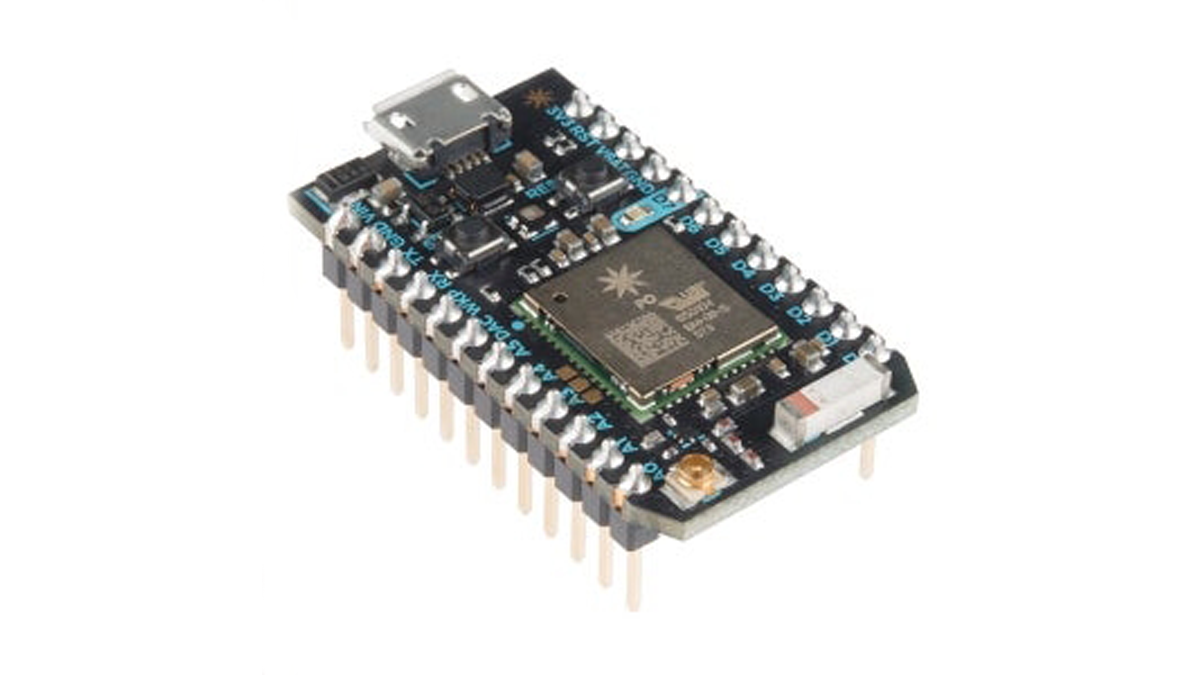
- Particle Photon
- [OPTIONAL] 2.4GHz u.FL antenna
- SparkFun OpenLog
- SparkFun Photon Weather Shield
- SparkFun Weather Meters
- Dallas DS18B20 Waterproof Temperature Sensor
- SparkFun Soil Moisture Sensor
- SparkFun Qwiic VEML6075 UV Light Sensor
- 3.5W solar panel
- SparkFun Sunny Buddy
- Custom 3D Modelled Stevenson Screen
- A soldering kit
- A bunch of single-core jumper wire
- A 2-pin screw terminal
- Some male and female headers
- 22 3mm stainless bolts
- 44 3mm stainless nuts
- 3 6mm stainless threaded rods
- 9 6mm stainless nuts
Step 1: The Hardware

Preparation
Weather Shield
As outlined in Sparkfun’s hookup guide, cut the RAW Power Select jumper pad on its back from VREG and solder itto Photon_VIN to reroute the incoming power line to the Photon’s internal voltage regulator for lower power consumption during sleep, which represents exactly half of the deploy time.
This will restrict the input voltage between 3.6 and 5.5V, but the power line falls right in the sweet spot with its 3.7V from the LiPo battery through the Sunny Buddy.
Also, make sure the 3.3V Disable jumper right below is connected: otherwise, the on-board sensors will not receive any power from the 3.3V line, making them effectively disconnected from the Photon.
This jumper is meant to be disconnected for operation on both external and USB power to avoid conflicts, and that is indeed the only situation that allows the on-board sensors to receive power and function properly. Don’t worry if you have to connect a USB cable to your Photon for some Serial monitoring: I have tried it myself many times, and the Photon has always survived safe and sound with no damage. Just maybe don’t leave it hours and hours on end like that.
Check out the shield’s schematic if you’re interested in more details.
Turning around the shield, make sure the I2C PU jumper pad on the right is connected.
The I2C bus, which includes the on-board sensors, requires a well-defined pull-up resistance by protocol standard, and having any other pull-up value will prevent the peripherals from being recognised: as a general rule of thumb, only one pair of pull-up resistors is to be connected on the bus. The sensor suite will involve another sensor on the bus — the UV light sensor — but as an I2C peripheral, that too comes with its couple of pull-up resistors, and I recommend disconnecting those instead: at least in this project, the shield can potentially be used all alone, while the UV sensor will hardly be used without the shield.
Soldering a screw terminal on the power connectors and some female jumpers on the peripheral connectors is also a good idea, and one I recommend for modularity: the quick connect and disconnect feature can turn out really helpful for troubleshooting, repairs, or upgrades. For a better fit and tidier cable management, make sure to connect the side ones on the back as shown in the pictures.
I also soldered jumpers on the Photon’s extension holes for even more modularity, but that’s not required as those pins are currently not used.
OpenLog
Cut and trim 4 short strands of wire, and solder them to the OpenLog as shown in the pictures.
It’s not jumper headers, but I found this to be the best solution for such a short connection. If you’re thinking about soldering some male header pins on the board and connecting those to the shield’s female headers, unfortunately the different pin layouts on the two interfaces prevent this great idea from being viable.
UV Light Sensor
Cut and trim 4 more strands of wire, much longer this time, and solder them to the board’s connectors as shown in the pictures.
Again, it’s not jumper headers, but I chose to value ruggedness over modularity in the connections which, like this one, are exposed to the elements and not protected by the enclosure. I also recommend twining the wires as I did for a cleaner and more practical connection. The other end, instead, is the place for jumper headers: solder 4 male pins to ensure that the connection is kept secured and ordered as intended over the long wires. Make sure to respect the order: as they go on the shield, GND VCC SDA SCL.
I also recommend coating the soldered contacts and the Power LED with a liquid insulator: conformal coating is specifically designed for this, but clear nail polish will do in a pinch, and that’s what I used. Despite the PMMA “roof” that will cover the board, it will still be exposed to the elements, and you’d rather be safe than sorry. Make sure not to cover the UV light sensor itself — the black chip in the middle of the board — especially if you’re using conformal coating: most compounds are UV-fluorescent, which means that they absorb some share of the light the sensor is trying to capture, therefore interfering with its readings. PMMA, on the other hand, is one of the most UV-transparent materials commonly available, and will sufficiently protect the sensor from the elements while still keeping its influence on its measurements to a minimum.
Soil Moisture Sensor
Trim the ends of the 3-strand cable, and solder them to the board’s connectors as shown in the pictures. And, at the other end, solder 3 male pins for a better connection. Again, make sure to respect the order: GND A1 D5.
For this sensor as well, make sure to coat the contacts and the on-board circuitry with the liquid insulator: unlike the UV light sensor, it won’t be covered by anything and will be completely exposed to the elements, so a good level of protection is needed.
Soil Temperature Sensor
Trim the ends of the cable and, again, solder them to 3 male pins in the order: GND D4 VCC. The close-ended wires are conventionally colour-coded: BLACK=GND WHITE=SIG RED=VCC.
Sunny Buddy
I soldered a couple of female jumper headers to the secondary Load connectors on the board, but ultimately ended up not using them, so that’s not necessary.
External Antenna
Simply stick the antenna on the base piece’s underside, or anywhere else that suits its form factor.
Calibration
Soil Moisture Sensor
This is the sensor that needs to be calibrated the most, and it’s important to calibrate it to the soil it will be monitoring once deployed.
To help with that, I’ve put together a simple program named calibrator.ino: just compile and flash it to your Photon, and get a serial monitor ready, for example with the Particle CLI command particle serial monitor or with screen /dev/ttyACM0. Put the sensor about three-quarters of its way inside the soil you want to calibrate it for, in a completely dry condition as shown in the first picture, and record this raw reading in the smCal0 field of the calibration.h file. Then, wet the soil as much as you can, until it’s saturated with water as shown in the second picture, and record this raw reading in that same file’s smCal100 field.
Sunny Buddy
Another element that requires calibration is the Sunny Buddy: while not a sensor, its MPPT (Maximum Power Point Transfer) design needs to be calibrated to that point of maximum power transfer.
To do that, connect it to your solar panel on a sunny day, measure the voltage across the SET and GND pads, and tweak the nearby potentiometer with a screwdriver until that voltage is about 3V.
Step 2: The Software
You can find all the code, updated and documented on its GitHub repo.
Step 3: The Assembly

Let’s start putting it all together with the Stevenson screen, starting assembling from the top-down as shown in the pictures.
First and foremost is the top cover, with its split stands for the UV light sensor and the solar panel to put together and bolt in. Next, to populate it, mount the solar panel on its rack and cover the UV light sensor with its PMMA roof. Then, the remaining covers can be assembled to the top piece with the threaded rods: the holes may need some convincing, but a bit of friction can help in keeping them all together.
Once the Stevenson screen is assembled, join the base piece with the rain gauge and populate it with its circuitry, by mounting the components on their boards and connecting them as shown in the pictures. Next, the peripherals such as the external antenna, the soil temperature and moisture sensors, and the OpenLog can be connected.
Then, you can put together the wind meters on their pole as shown in SparkFun’s assembly guide, and mount the rain gauge and the base piece about three-quarters of its way up.
You can then proceed to route the cables coming from the solar panel, the UV light sensor, and the rain and wind meters through an opening between the covers and mount the Stevenson screen on the base piece. Once the rods are secured with a couple of nuts on each one, your very own personal weather station is complete and ready to be deployed on the field!
Step 4: Deployment + Conclusions
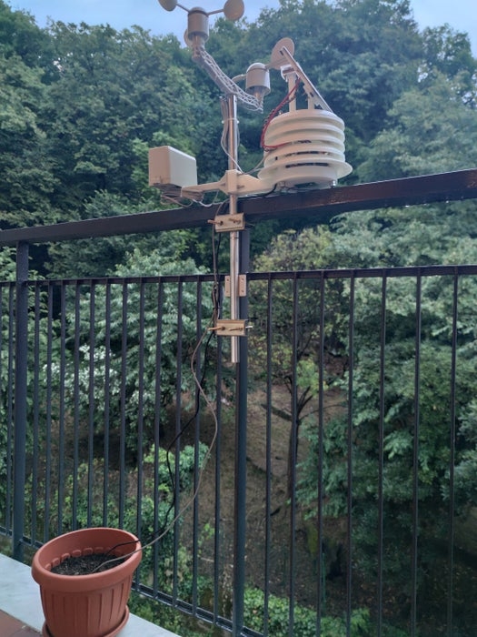
Once you’ve completed that, you can sit back, relax, and enjoy seeing your live hyper-local weather data on all the following platforms!
The specific links above are to my weather data, but if you make this project too, please include the links to your devices as well — I’d really love seeing this people-made network expand!
Source: Particle Photon IoT Personal Weather Station