Summary of Painless WiFi on Arduino
This article details a method to create an Arduino WiFi project that avoids the tedious DIP switch toggling required by many ESP8266 boards. By configuring the Arduino Mega's Serial3 port for WiFi communication and using the USB port for debugging and uploads, developers can maintain a smooth development cycle without hardware conflicts. The guide covers circuit setup, switch configuration, code implementation, and migration to an Arduino Uno.
Parts used in the Arduino WiFi Project:
- Arduino Mega + ESP8266 WiFi board
- Breadboard
- 3 LED's
- 3 current limiting resistors (440+ ohm)
- Hookup wire
- Arduino Uno (optional for final deployment)
- Duinotech ESP13 WiFi shield or similar (optional)
- Power supply (e.g., phone charger or 9V pack)
- Network communications program (netcat)
Communication with the outside world is a great feature for Arduino Projects and mandatory for many of them.
In this instructable, we will, painlessly, create an Arduino WiFi project that allows you to send it commands to turn on/off LED’s connected to the Arduino from a computer over your WiFi.
The development cycle will be as follows:
- we will use an Arduino Mega+ESP8266 WiFi board for development and debugging.
- Once it is working properly we will move that project to an Arduino Uno + ESP8266 WiFi Shield.
You could also use an Arduino Uno+ESP8266 WiFi board at step 2 or any other combination that uses the ESP WiFi shield.
This Instructable is also readily adaptable to other hardware that, like the ESP8266 WiFi uses the main “Serial” device on Arduino to interact with it – e.g. many Bluetooth modules.
If your preference is to jump right in and wish to skip the background, simply jump to the next step and start hooking things up, uploading code and entering commands. You can always come back and revisit this later if you wish to.
There are lots of options for Arduino communications, I often use Wired Ethernet or USB because I have that infrastructure available to me, it is generally easy to use and works for me. But there are times when a Wireless approach would be much easier.
There are plenty of wireless connectivity options available such as LoRa, Bluetooth, IR, WiFi and more. Each of them have different attributes and ideal use cases. Arguably the most ubiquitous is WiFi which is what this article is about.
However, all of the WiFi solutions for Arduino that I have (ESP-8266 solutions) and others that I have read about online seem, IMHO, quite tedious (i.e. painful) to work with. The Arduino project development cycle requires hardware hacks and / or constant switching of DIP switches to work with them.
The tediousness that I allude to is due to the fact that interaction between the Arduino and the WiFi hardware is via the Arduino’s “Serial” device. The Arduino Serial device is, by default, used for two things:
- The IDE’s Serial monitor for interaction with the program running on the Arduino (e.g. debug messages)
and - the uploading of new programs to the Arduino.
The shared use of Serial by Arduino and the WiFi is to all intents and purposes a conflict – that is, is Serial being used to upload a new program(/sketch) to Arduino, or is it being used to send commands to the WiFi or is it being used to output debug messages? The solution to this conflict implemented on many WiFi board is to use a series of DIP switches or require additional hardware to resolve the dilemma of what the Serial port is being used for.
This means that when you are developing your Arduino program and want to upload it after making a change, you need to set the DIP switches to a “certain configuration” (Serial device is connected to the USB) to allow the updated program to be uploaded.
When you are done uploading and want to run your new code, you need to set the DIP switches to a different “certain configuration” (Serial device is connected to the WiFi) and reset your Arduino so as to restart the program – or have some other mechanism that causes the program to wait before starting to issue WiFi directives (e.g. a delay to allow you time to reset the switches or the press of a button etc).
Of course if you have debug messages in your program that normally are output to the Serial device and thus visible in the Arduino IDE’s Serial Monitor, you are out of luck as the these debug messages will be sent to, you guessed it, to the WiFi device which will unlikely be able to process them.
After testing, you identify a new code change, add a new feature or whatever then need to reset the switches for upload then re-reset the switches to run your modified ode. You need to repeat this cycle every time you change your code – no matter how small the change is.
To me, this is extremely tedious and on some boards, the switching of the switches has a risk of damaging it if you are not careful – or put another way, this, IMHO, is extremely painful!
One option is to use a SoftwareSerial or if you have it, another Serial port (e.g. Serial1 on Leonardo) for debug messages or WiFi interaction, but this would require some sort of converter (e.g. another Arduino, a FTDI USB-Serial converter etc) to connect the SoftwareSerial/Serial1 “port” to a PC and so on. And doesn’t resolve the main problem of the main Serial device being used for both program upload as well as communication with the WiFi module.
Another potential problem that I have encountered when using SoftwareSerial, which I found particularly frustrating, is that for each communication with the WiFi board I often need to output several debug messages to isolate a problem. This can (and has) resulted in loss of data, corrupted messages on the Serial monitor and other issues. Which means that you might be trying to debug a problem that really doesn’t exist as it is simply caused by the load passed through SoftwareSerial. In my testing, this “data overrun” problem did not seem to occur when the same debugging messages were sent via a hardware serial port.
So this article is about how to avoid the pain and have a normal development cycle of code, upload, test, repeat as needed – without the DIP switch pain to workaround the Serial conflict problem.
Supplies
This project primarily uses the Arduino Mega + WiFi for the development cycle.
Once your project is done, we will port our code to an Arduino Uno + WiFi (or any other Arduino with the ESP WiFi shield).
So the parts list is:
- Arduino Mega + WiFi board (available from Jaycar XC-4421)
- One medium sized Breadboard
- 3 LED’s
- 3 current limiting resistors (440+ ohm)
- hookup wire
Optionally
- Arduino Uno
- Duinotech ESP13 WiFi shield or similar (available from Jaycar XC-4614)
or - Arduino Uno + Wifi board (available from Jaycar XC-4411)
- You will also need a power supply for your Uno. I just use an old phone charger and the USB cable that you used for your Arduino. But you could also use, say, a suitable 9V power pack with a barrel plug – please check that it is Arduino friendly (DC, voltage is OK, polarity of the plug etc) before plugging it in!
You will also need a network communications program. I use netcat which is available for
- Linux – sudo apt-get install netcat
- MacOS – brew install netcat
- Windows – while there are standalone versions “out there”, I use the version that comes with cygwin.
Step 1: Hooking Up the Components
In this project, we will build software on the Mega and later migrate the code (and test circuit) to the Uno.
You will need the following components:
- Arduino Mega+WiFi
- Breadboard
- 3 LED’s and current limiting resistors
- Hookup Wire
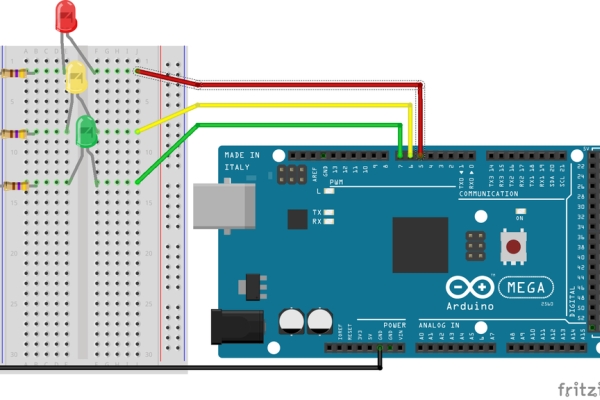
The circuit is fairly straightforward (refer to the diagrams), so I won’t explain it in any detail. Make sure you connect the LED’s with the flat side/short leg to the resistors, which are in turn connected to ground.
The test program uses Digital I/O pins 5, 6 and 7, so connect the LED’s (via the long legs) to these pins on the Arduino Mega. I used different colour LED’s, but you don’t have to if you do not have multiple colours. Also, if you do have different colours, the order doesn’t really matter, simply connect one LED (+ current limiting resistor) to each of the DIO pins 5, 6 and 7.
The photo, breadboard and circuit diagrams illustrate how the connections are made.
Step 2: Setting the DIP Switches on the Mega
On the Arduino Mega+WiFi, you should find 2 sets of switches that I have highlighted in the photo. On my board one switch is a 8 way DIP switch block (with tiny little switches that require a tool – e.g. small screwdriver – to move). The other switch is a larger switch which is in the form of a slider.
To try to minimise confusion, I will refer to the main serial port that is available on all Arduino boards as Serial(0). In code, this is the serial device that is named Serial and is normally connected to the USB port on Arduino boards.
The first block of 8 switches control the primary communications paths on the board. The options include:
- Connect the Mega’s Serial port to the ESP (switches 1&2 on)
- Connect the USB to the Mega’s Serial(0) port (switches 3&4 on)
- Connect the USB to the ESP (switches 5&6 on)
- Cause the ESP to enter programming mode on next reset (switch 7 on)
- Switch 8 is unused.
The second large switch determines how (i.e. by which path) the Mega is connected to the ESP (switches 1&2 on). This switch controls which of the Mega’s Serial ports is used to communicate with the ESP. The choices are Serial(0) or Serial3.
What this means is that we can:
- use the Mega’s Serial3 port to communicate with the ESP and hence utilise its WiFi capabilities.
and - Use the USB in the traditional way to upload code to the Mega and interact with the Mega’s program via the Serial Monitor without having to constantly adjust switches 1&2 and switches 3&4 while programming and testing.
In short, this switch resolves the hardware conflict associated with the Serial(0) port that I outlined in step 1.
To set this up, configure the switches as follows:
- Turn switches 1, 2, 3 & 4 -> ON.
- Turn switches 5, 6, 7 & 8 -> OFF.
- The big slider should be set to the end with the TXD3 and RXD3 end (i.e. positioned away from the USB connector and the 8 way DIP switch).
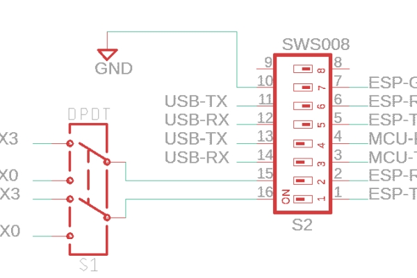
The circuit diagram shows how I believe that the two switches are likely to be connected. I say this because I’ve found lots of diagrams online that (how can I say this?) do not appear to accurately reflect the actual circuitry on the board – some might say that the diagrams I found were “completely wrong”.
I produced this circuit diagram from extensive testing/trial and error. In my diagram, it is possible that I have the TX and RX lines reversed on each switch pair, but this shouldn’t matter as the switches should always be used in pairs (i.e. switches 1&2 should be set the same way, similarly 3&4 should be set the same way as should switches 5&6).
Step 3: Develop Your Arduino WiFi App
Since I will provide the Arduino code, there won’t be much of a development cycle, but I will try to illustrate the development cycle by suggesting a change to illustrate that we can painlessly re-upload and run the modified code in the next step.
The key takeaway is that we can do this without constantly changing the switches and without extra supporting hardware. We will see how to configure the Arduino Mega + WiFi so that you can use the Arduino <-> PC USB connection to:
- upload compiled code,
- interact with the code running on Arduino via the Serial Monitor
and - use the WiFi.
All without having to constantly change the DIP switches on the board.
Having said that, we will need to do an initial setting of the switches on the Arduino Mega+WiFi to support this development process (as described in the previous step). If you haven’t set the switches yet, please go back to the previous step and do so now.
The code we will use for our development can be downloaded from my GitHub or copied and pasted from below.
Note there are two files. The first file can be named anything you like (I called mine ArduinoESPInteractive.ino). The second file must be named NullSerial.h.
Simply create a new project in the Arduino IDE and use the code from the two files shown below or from GitHub.
If you are entering the code manually or copy/pasting then you will also need to manually add the second file. To add the second file, simply click the little down arrow on the top right hand side of the Arduino IDE editor and choose “new tab” then name it NullSerial.h
Ensure that you have set the DIP switches on your Mega+WiFi as described in the previous step.
Upload the Code as per usual. Open the Serial Monitor, set the baud rate to 115200, observe some startup messages which I will describe in the next step.
Here is the main program (ArduinoESPInteractive.ino):
/***********************************************
 * MegaESPInteractive
 * ------------------
 *
 * This program is designed for use with an Arduino Mega + ESP 8266 combo board.
 * It allows you to:
 * - interact with the ESP 8266 via the Arudino
 *   and
 * - upload programs to the Arduino
 * without constantly switching the DIP switches to connect the Arduino to the ESP
 * and/or the USB.
 *
 * If you want to upload a program to the ESP, you will still need to set the DIP
 * switches.
 *
 * The ability to have a development cycle that does not involve switching DIP
 * switches expedites the program/debug cycle of WiFi based apps because the very
 * tedious and fiddly step of constantly having to change them is eliminated. This
 * will also probably extend the life of the board as you don't have as much
 * mechanical wear and tear on them.
 *
 * Hardware required:
 * - Arduino Mega + ESP 8266 wifi combo board such as the Jaycar XC4421:
 *      https://www.jaycar.com.au/mega-with-wi-fi/p/XC4421.
 * - optionally an FTDI USB - Serial board such as the Jaycar XC4672:
 *      https://www.jaycar.com.au/isp-programmer-for-arduino-and-avr/p/XC4627)
 *
 * The development cycle works as follows:
 * 1) Develop your code and upload using the standard Arduino IDE upload mechanism.
 * 2) use Serial3 (via a preprocessor #define constant) for interaction with the
 *    ESP.
 * 2) Optionally interact with your Arduino program via Serial2 or Serial (also via
 *    a preprocessor constant)
 * 3) Output Debug messages to Serial (via a preprocessor constant).
 *
 * Preprocessor symbols are used to represent the two Serial ports used as follows:
 *   ESP -> Serial3
 *   HOST-> Serial or Serial2
 *
 * Once your program is complete and can operate standalone, you can transfer to a
 * smaller device (e.g. the Arduino UNO + Wifi board). Simply redefine the constants
 * so that ESP is Serial and HOST is an instance of softwareSerial.
 *
 * To use this program, two sets of switches on the Arduino Mega+ESP8266 Wifi must
 * be set as follows:
 *
 * The large DPDT switch with labels RXD0 & TXD0 at one end and RXD3 & TXD3 must be
 * set to the RXD3 & TXD3 end. This enables the Mega Serial3 port for communications
 * with the ESP.
 *
 * The 8 position DIP switch must be set as follows:
 *
 *    on      o  o  o  o
 *    off                 o  o  o  o
 * Number     1  2  3  4  5  6  7  8
 *
 * That is, switches 1, 2, 3 & 4 are be turned on and
 * switches 5, 6, 7 & 8 are turned off.
 * These switch configurations:
 * - Connect the Mega Serial3 to the ESP (for WiFi access)
 * - Connect the Mega Serial to the USB (for programming and debugging).

 */
#include "NullSerial.h"

#define VERSION "1.1.0.1"
/*
 * Revisions.
 * 1.1.0.1
 *    Corrected bug for LED on/off debug messages.
 *
 * 1.1.0.0
 *    Added concept of debug messages.
 *    Added initialisation of WiFi to station mode and connect to WiFi boiler
 *    plate code.
 *
 */

#if defined(ARDUINO_AVR_MEGA2560)
  #define HOST_BAUD 115200
  #define HOST_RX  "USB(0)"
  #define HOST_TX  "USB(1)"
  #define HOST  Serial
  #define DEBUG Serial

//  NullSerial _debug(1, 2);
//  #define DEBUG _debug

  #define ESP_BAUD  115200
  #define ESP_RX  15
  #define ESP_TX  14
  #define ESP   Serial3

#else if defined(ARDUINO_AVR_UNO)
/*
 * On Uno, we only have one hardware serial device.
 * So, we will use SoftwareSerial for any interactions that may be required with
 * the host.
 */
  #include <SoftwareSerial.h>
  #define HOST_BAUD 115200
  #define HOST_RX  10
  #define HOST_TX  11
  SoftwareSerial _host(HOST_TX, HOST_RX);     /* (my_RX, my_TX) */
  #define HOST  _host

  NullSerial _debug(HOST_TX, HOST_RX);
  #define DEBUG _debug
//  #define DEBUG _host

  #define ESP_BAUD  115200
  #define ESP_RX  "USB(0)"
  #define ESP_TX  "USB(1)"
  #define ESP   Serial

#endif

/* A pair of macros that allows the value of symbols defined in #define
 * preprocessor directives (e.g. HOST) to be output as strings (e.g. in
 * print function calls).
 */
#define _STRING(x) (#x)
#define STRING(x) _STRING(x)


/*****************************
 * The hasEOLJustBeenSent is used to track whether an end of line has been sent to
 * the ESP.
 * The version of code shipped with the device requires a Carriage Return (CR)
 * followed by a Line Feed (LF) - in that order - to mark the end of a line (EOL).
 * That is, the ESP requires a CRLF end of line (EOL) sequence.
 *
 * This program allows you considerable flexibility of windows terminal programs
 * (I use Putty, CoolTerm, the Arduino Serial monitor and others) in their default
 * configurations. These programs all generate various combinations of the common
 * line endings CR only, LF only and CRLF.
 * When it sees a CR ('\r') or LF ('\n'), the program will send an EOL to the ESP.
 * To allow for terminal programs that send both a CR and a LF, the
 * hasEOLJustBeenSent is used to track that an EOL has been sent when either the CR
 *  or LF is received from the HOST.
 * To prevent doubling up on EOL's, if we have just received a CR or LF, and the
 * next character is also a CR or LF, then it will simply be ignored.
 */
boolean hasEOLJustBeenSent = false;
char buf[100];
int bufPtr = 0;

boolean OKseen = false;
boolean ERRORseen = false;
boolean FAILseen = false;
boolean TIMEOUTseen = false;


/*
 * processInput(msg)
 * -----------------
 *
 * Processes a message received from the ESP.
 * This includes processing responses to commands (e.g. OK, FAIL etc)
 * Processing input from a client.
 * Processing client connection/disconection messages.
 * And others as required.
 *
 */
void processInput (const char * msg) {
  DEBUG.println();
//  DEBUG.print(F("Received: "));
//  DEBUG.println(msg);

  OKseen = false;
  ERRORseen = false;
  FAILseen = false;

  if (strncmp(msg, "+IPD", 4) == 0) {   // Client message?
    DEBUG.println(F("Received input from client"));
    char led = msg[9];                  // Extract the LED number
    char setting = msg[10];             // Extract the setting (on/off)
    if (led >= '1' && led <= '3') {     // Check the LED number for validity (i.e. 1, 2 or 3)
      led = led - '1';                  // if valid, convert to an integer.
    } else {                            // Otherwise print an error message to the USB.
      HOST.print(F("Invalid LED: ")); HOST.println(led);
      return;
    }

    DEBUG.print(F("Setting LED ")); DEBUG.print(led);
      DEBUG.print(F(" on DIO ")); DEBUG.print(led + 5);
      DEBUG.println(setting == '+' ? " on" : " off");
                                              // FInally, turn the requested LED on or off
    digitalWrite(led + 5, setting == '+');    // depending upon the value in "setting".
                                              // The led + 5 adjusts the LED value (0, 1 or 2)
                                              // to the corresponding Arduino digital I/O pins
                                              // which that have LED's connected whihc are pins 5, 6 & 7.
  }
  OKseen = strcmp(msg, "OK") == 0;
  ERRORseen = strcmp(msg, "ERROR") == 0;
  FAILseen = strcmp(msg, "FAIL") == 0;
}


/*  accumulateESPData
 *  =================
 *
 *  Check if a character is available on the ESP Serial port.
 *  If it is, accumultate the character in a buffer.
 *  When a newline is observed, process the input.
 *
 *  Returns true when a newLine has been seen and the input processed.
 *          false otherwise
 */
boolean accumulateESPData() {
  boolean newLineSeen = false;

  if (ESP.available()) {
    char ch = ESP.read();
    HOST.write(ch);
    if (ch == '\r' || ch == '\n') {
      buf[bufPtr] = '\0';           // Null terminate the input;
      if (bufPtr > 0) {
        processInput(buf);
        newLineSeen = true;
      }
      bufPtr = 0;
    } else {
      if (bufPtr < sizeof(buf) - 1) {   // Append the character to
        buf[bufPtr++] = ch;         // the input buffer if space permits.
      }
    }
  }
  return newLineSeen;
}


/**
 * sendESP(msg)
 * ============
 * Send the supplied msg to the ESP along with a CRLF line ending.
 * Wait for a response of OK, ERROR, FAIL or a TIMEOUT.
 * The timeout period is specified by the toPeriod constant value.
 */
const unsigned long ESP_TO_PERIOD = 30000;    // millis to wait for reply (30 secs).
void sendESP(const char *msg) {
  ESP.print(msg);
  ESP.print("\r\n");
  OKseen = false;
  ERRORseen = false;
  FAILseen = false;
  TIMEOUTseen = false;
      // Establish the initial timout period.
  unsigned long timeout = millis() + ESP_TO_PERIOD;
      // Loop until we get one of the expected replies
      // or a timeout occurs (without getting one of the expected replies)
  while (!OKseen && !ERRORseen && !FAILseen && ! TIMEOUTseen) {
    if (accumulateESPData()) {
            // A response has been recieved.
            // Debug output the status of the expected replies
      DEBUG.print(F("O,E,F="));
        DEBUG.print(OKseen); DEBUG.print(ERRORseen);
        DEBUG.println(FAILseen);
      timeout = millis() + ESP_TO_PERIOD;    // message rcvd, reset the timer.
    }
    if (millis() >= timeout) {
      TIMEOUTseen = true;
      DEBUG.println(F("*** Timeout waiting for ESP reply"));
    }
  }
}


/**
 * AccumulateHOSTData
 * ==================
 *
 * Check for data being available from the host. If there is data, simply pass it on
 * to the ESP.
 * If a CR or a LF is observed in the HOST data, send the ESP a CRLF.
 */
void accumulateHOSTData() {
  if (HOST.available()) {
    char ch = HOST.read();
//    HOST.write(ch);                   // Perform local echo to HOST (or not)
    if (ch == '\n' || ch == '\r') {   // Do we have a LF or CR?
      if (!hasEOLJustBeenSent) {      // Yep, did we just send one?
        ESP.write('\r');              // Nope, so send a CRLF to the ESP.
        ESP.write('\n');
        hasEOLJustBeenSent = true;    // Track that we've sent an EOL
      }
    } else {                          // Not a CR & not a LF, so
      ESP.write(ch);                  // Write the character to the ESP
      hasEOLJustBeenSent = false;     // Since not a CR & not a LF, track that
                                      // we didn't just send an EOL to ESP.
    }
  }
}


/**
 * setup
 * -----
 *
 * Initialise our Serial devices, output some configuration information
 * and set the BUILTIN_LED for output.
 */
void setup() {
  ESP.begin(ESP_BAUD);
  HOST.begin(HOST_BAUD);
  while (!HOST) {
    delay(1);
  }

  HOST.print(F("Version: ")); HOST.println(F(VERSION));
  HOST.print(F("ESP  Ready on: ")); HOST.print(STRING(ESP));
    HOST.print(F(" @ ")); HOST.print(ESP_BAUD);
    HOST.print(F(" bps. RX, TX: "));
    HOST.print(ESP_RX); HOST.print(F(", ")); HOST.println(ESP_TX);

  HOST.print(F("HOST Ready on: ")); HOST.print(STRING(HOST));
    HOST.print(F(" @ ")); HOST.print(HOST_BAUD);
    HOST.print(F(" bps. RX, TX: "));
    HOST.print(HOST_RX); HOST.print(F(", ")); HOST.println(HOST_TX);

  DEBUG.println(F("**** Debug messages enabled ****"));
  HOST.println();

  pinMode(5, OUTPUT);             // Set some pins to output for LEDs.
  pinMode(6, OUTPUT);
  pinMode(7, OUTPUT);

  DEBUG.println(F("Sending GetVersion"));
  sendESP("AT+GMR");              // Get Version Info.
    // Once off set mode and join the WiFi.
  DEBUG.println(F("Setting the mode"));
  sendESP("AT+CWMODE=1");         // Set operating mode to "station"
  DEBUG.println(F("Connect to my WiFi"));
  sendESP("AT+CWJAP=\"YourWiFi\",\"yourpassword\"");

  DEBUG.println(F("Sending Max Connections=1"));
  sendESP("AT+CIPMUX=1");         // Enable Server
  DEBUG.println(F("Sending Start Server on Port 80"));
  sendESP("AT+CIPSERVER=1,80");   // Open port 80

  HOST.println(F("Ready"));
  HOST.println();
}


/* Loop
 * ====
 *
 * Accumulate characters from the HOST and ESP.
 * Process them as necessary.
 */
void loop() {
  accumulateHOSTData();
  accumulateESPData();
}
Here is the second file. It must be named NullSerial.h and be in the same folder as the main program (from above). I will explain the purpose of this file when we move our project to the Arduino Uno + WiFi.
/*
 * NullSerial
 * ----------
 *
 * An empty implementation of a Serial Interface.
 *
 * The idea for this NullSerial class is to, via conditional compilation,
 * eliminate any Debug messages from released code.
 *
 */

 #ifndef NullSerial_h
 #define NullSerial_h

class NullSerial {
  public:
    NullSerial(uint16_t receivePin, uint16_t transmitPin, bool inverse_logic = false) {}
    NullSerial() {}
    void begin (long speed) {}
    bool listen() { return false; }
    void end() {}
    bool isListening() { return false; }
    bool stopListening() { return false; }
    bool overflow() { return false; }
    int peek() { return -1; }

    void println() {}
    void print() {}
    void println(const void * msg) {}
    void print(const void * msg) {}
    void println(const int i) {}
    void print(const int i) {}
};

#endif   //NullSerial_h
Source: Painless WiFi on Arduino
- How do I avoid switching DIP switches during development?
Configure the Mega to use Serial3 for the ESP and the USB/Serial0 for the IDE and debug messages. - Which pins should I use to connect the LEDs?
Connect the LEDs via current-limiting resistors to Digital I/O pins 5, 6, and 7. - What is the correct setting for the large slider switch on the Mega?
Set the slider to the end labeled RXD3 and TXD3, positioned away from the USB connector. - Which DIP switch positions must be turned ON?
Switches 1, 2, 3, and 4 must be turned ON, while switches 5, 6, 7, and 8 are turned OFF. - What baud rate should I set in the Serial Monitor?
The Serial Monitor should be set to a baud rate of 115200. - Can I use this method with an Arduino Uno?
Yes, but you will need to redefine constants to use SoftwareSerial for the host connection since the Uno has only one hardware serial port. - What network tool does the author recommend for sending commands?
The author recommends using netcat, which is available for Linux, MacOS, and Windows. - Why is the NullSerial.h file included in the project?
It provides an empty implementation of a Serial Interface to eliminate debug messages from released code via conditional compilation.