Introduction
When our team was initially assigned the task of transforming this project from a cinematography quadcopter to a more practical sensor quadcopter, we made the decision to redesign the frame. This decision was not taken lightly, but it was concluded that one of the reasons the drone had been unable to fly thus far was due to the additional weight that only served to protect it in the event of a fall, assuming it managed to take off at all. The new frame would be significantly lighter while still maintaining sufficient structural integrity to withstand the forces exerted by various drone components. In order to minimize costs, we made an effort to salvage all electronics from previous iterations. Consequently, we also opted to remove the microcontroller and sensors from the drone in a manner that would allow the same sensor package and code to be used with any other drone equipped with a standard camera mounting knuckle system. This approach aligns with the principles of open source, as many consumer drones already possess such a mounting system, and acquiring a new drone is unnecessary for individuals who only require the sensor package. Thus, the project became divided into two main aspects: creating the drone itself and developing the sensor package.
Objectives and Constraints
A. Objectives
The primary objective of this project is to develop a functional drone capable of flying, alongside the creation of a separate sensor package that can be integrated into this drone as well as other drones, enabling data collection and storage. The project emphasizes the utilization of open-source manufacturing practices and consumer-grade components. The following goals have been established:
1. Open-Source Part Files for Modification:
– The parts have been designed using Onshape, a freely available CAD software.
– The part files will be shared in the PARASOLID format, which is compatible with various CAD software, allowing for easy access and modification.
2. Open-Source Controller Hardware:
– The flight controller chosen for this project is the MATEKSYS F405-miniTE, running iNAV.
– This choice enables the community to utilize different styles of iNAV-supported flight controllers to cater to their specific needs and functionalities.
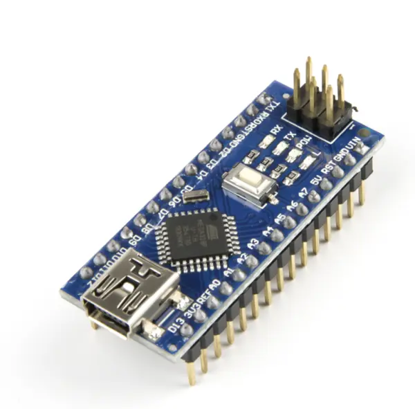
3. Arduino Nano for Sensor Control/Data Acquisition and Logging:
– The Arduino Nano board is employed to manage sensor control, acquire data, and facilitate data logging.
4. 3D Printed Components:
– The incorporation of 3D printed components enables cost-effective manufacturing of both new and existing parts.
5. Perform Basic Quadcopter Flight Maneuvers:
– The drone is designed to execute fundamental quadcopter flight maneuvers.
– It can be controlled using a handheld transmitter.
– Ensuring safe takeoff and landing.
– Offering precise and accurate controls during flight.
6. Sensor Package:
– The sensor package is engineered to interface with various sensors.
– It is capable of logging data effectively.
B. Constraints
To ensure accessibility for open source enthusiasts, the design of the project is subject to certain limitations, which are as follows:
1. Open-Source Tools for Frame Manufacturing:
– The quadcopter frame will be manufactured using open-source tools.
2. 3D Printing as the Manufacturing Method:
– The primary manufacturing approach for this project will be 3D printing.
3. Structural Resilience:
– The quadcopter frame must possess the necessary strength and durability to withstand the forces experienced during flight.
4. Cost Limitation:
– Any modifications or changes made to the previous designs should not exceed a budget of $100.
5. Time Frame:
– The project is expected to be completed within a single semester timeframe.
Drone Rework
A. Frame
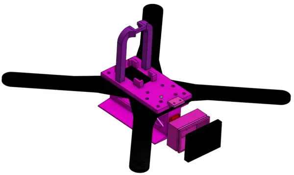
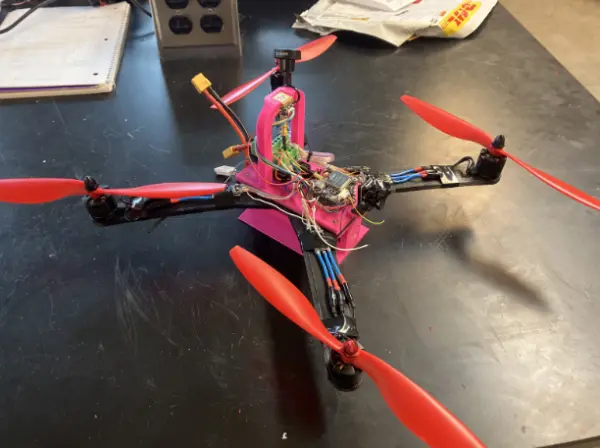
Upon receiving the non-functional drone, our team’s initial objective was to strip it down to its simplest form and then gradually rebuild it with the aim of achieving flight capability. To achieve this, we opted to discard the previous frame utilized by the previous project team and replace it with a lighter and more manageable alternative. To align with this objective, it was determined that employing flat arms fabricated from ABS (to enhance ductility) and printing the frame’s center using PLA would be the most suitable approach. Figure 1 illustrates the design in Onshape, while Figure 2 showcases the printed frame with the electronics securely mounted.
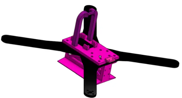
The redesigned frame incorporates individual arms, allowing for easy replacement of any broken arm and reducing the required size of the 3D printer for replication purposes. By mounting the battery vertically, accessing the undercarriage becomes more convenient, and additional mounting points for sensors are made available. Furthermore, this configuration provides a consistent flat base for gyroscope calibration, as opposed to relying solely on the screws located at the bottom of the frame.
Additionally, this new design facilitates the mounting of motor speed controllers (ESCs) on the arms, creating more space in the central area of the frame. This increased space is beneficial for accommodating the flight controller and vision system, which will be further discussed later on.
B. Vision
In the previous iteration of the drone, a Runcam hybrid camera with an integrated video logger was utilized. This camera system operated using a spare UART on the flight controller, enabling remote control over video recording. Unfortunately, during the electronic overhaul, the camera logger was damaged, resulting in the complete shearing off of one of the pads. While this camera system would have been compatible with the vision-related modifications, we opted for more cost-effective alternatives.
While a video system is not an essential requirement for a drone focused on sensors and autonomous navigation, it significantly improves the user experience. Having access to metrics such as satellite count and error messages proves highly useful for troubleshooting purposes. Therefore, I would recommend incorporating a First Person View (FPV) camera, a video transmitter (VTX), and a video receiver (VRX). Analog video transmission is used in this setup, which is compatible with most analog VRX systems. While any VTX and camera combination can be used, I utilized a Caddx Ratel 2 camera and a Wolfwhoop Q3-S video transmitter. As for the VRX, I utilized my Skyzone 04X goggles, although there are also VRX systems available with A/V outputs that can be connected to monitors accepting A/V input. With this vision setup, real-time viewing of errors and data becomes possible, and adjustments can be made through the OSD settings in iNAV.
C. Final Wiring Diagram
Final Comments on Drone Build
To conduct indoor motor thrust testing, it was necessary to disable the GPS and magnetometer functionalities. It is important to note that arming a drone indoors, especially of this size, is not recommended practice due to safety concerns. If future project replicators wish to reinstate these functionalities, they would need to enable GPS on UART 5 and add the ICM42605 accelerometer, QMC5883 magnetometer, and SPL06 barometer options in the sensors and buses settings.
Using 3D printed frames for drones is not as common as using carbon fiber frames. This is primarily because 3D printed frames tend to be heavier than carbon fiber frames and may not provide the same level of stability expected by the flight controller. There are open-source drone frames available, as well as services like CNCmadness that specialize in cutting carbon fiber for drone frames. Considering the weight issue and underpowered motors inherited by the current state of the drone, it is currently incapable of flying. For those intending to replicate this project, it would be advisable to consider using prebuilt drones or components specifically designed for this type of system.
Additionally, the open-source RC control link ELRS (ExpressLRS) is highly recommended, as it has been extensively developed by the community and is regarded as one of the best and most user-friendly control links in the market. Most modern flight controllers can be flashed with iNAV firmware, and modern 4-in-1 speed controllers simplify the wiring process compared to using separate speed controllers and battery breakout boards. Upgrading to modern flight controllers and speed controllers can streamline the build process and support more powerful motors, which are necessary for effectively spinning a 10-inch propeller and adequately lifting a drone of this weight.
The sensor logger has been designed to fit a standard knuckle system that is commonly included in many drones currently available in the market. It can be adapted to various platforms. The casing model is solidly printed, allowing for the drilling of holes to accommodate wires going in and out of the microcontroller. If water resistance is required without conformal coating the microcontroller, the holes can be sealed with silicone or hot glue. Depending on the specific use case, a multirotor may not be the ideal platform for the required sensors, and a more traditional plane design might be more suitable. This flexibility is the reason the sensor system was designed to be removable and attachable to any platform that fits a particular use case.
Arduino Sensor Pack
A. Setup
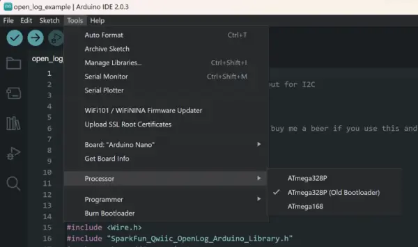
Before uploading any code to an Arduino Nano, there are two prerequisites that must be fulfilled. The first requirement is to install the appropriate drivers, which will be discussed in the following instructions. The second step involves selecting the correct processor. Please choose the old bootloader option, as depicted in the figure provided below.
To determine if the Arduino board in use is not genuine, please refer to the two images displayed below. Observe the contrasting shades of blue and the varying styles of the reset button. The first image portrays a generic microcontroller, in which case the drivers provided in Appendix A should be installed. Additionally, please note that in the Arduino, the SCA (Serial Clock Line) corresponds to pin A4, while the SCL (Serial Data Line) corresponds to pin A5.
If an uploading error is given after these steps are taken, it is possible that the Arduino is fried.
B. Sensors
Openlog
This is the data logger that writes all of the measurements to a micro-SD card.
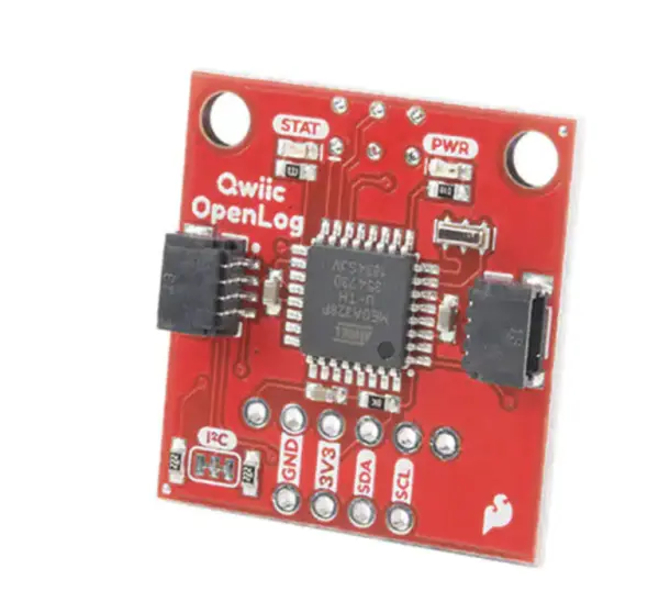
Pinout for connectors
| Pin on sensor connector | function |
| top | SCL |
| 2nd to top | SDA |
| 2nd to bottom | 3 V power |
| bottom | gnd |
SGP30
This is the air quality sensor. It measures CO2, Total Volatile Organic Compounds (TVOC), and alcohol density.
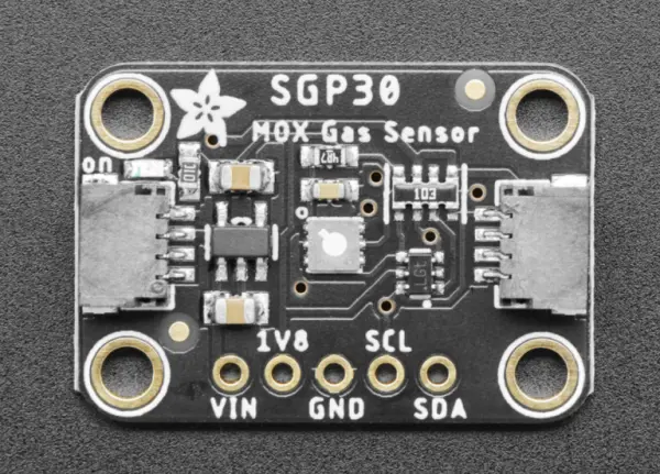
Pinout for connector
| Pin on sensor connector | function |
| top | SCL |
| 2nd to top | SDA |
| 2nd to bottom | 3 V power |
| bottom | gnd |
Sensirion
This is our humidity sensor.
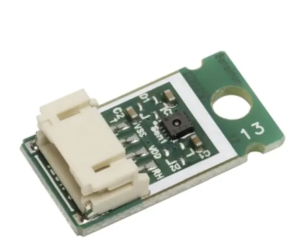
Pinout for connector
| Pin on sensor connector | function |
| left | SCL |
| 2nd to left | gnd |
| 2nd to right | 3 V power |
| right | SDA |
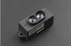
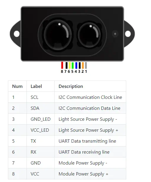
Lidar
This is used to measure distances.
Electrical/Mechanical Hardware Assembly Procedure
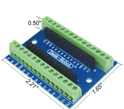
The Arduino is integrated within a screw terminal, as depicted in the image below. The sensors, on the other hand, are equipped with connectors featuring bare wires at their ends, allowing for easy connection to the terminal. For specific pinout details, please refer to Section VI of the Arduino Sensor Pack documentation.
Final Comments on Microcontroller integration
A significant portion of the semester for the Arduino sensor pack team was dedicated to inventory management and validation of the provided hardware. They meticulously examined the datasheets of all the sensors to ensure accurate pinouts. To validate certain sensors like the SGP30 and openlog, they referred to code that had been previously published online. As a result, it was confirmed that the SGP30 sensor still functions properly, while the openlog encountered issues.
In future iterations of the Arduino sensor pack project, it would be advantageous for the team to solder jumper cables onto the sensors. This would allow for easier integration with breadboards, significantly expediting the troubleshooting process and potentially aiding in diagnosing any problems with the openlog sensor. Once the issue with the openlog is resolved, the team can explore options such as designing a custom PCB to establish connections between the Arduino and the sensors, or creating custom connectors to achieve the same objective.