
Summary of OBJECT TRACKING CAMERA SLIDER GETS THE NICE SHOTS
This article describes a motorized camera slider with object tracking capabilities built by Saral Tayal. The project enhances standard sliders by using an Arduino Uno, RoboClaw controller, and encoders to rotate the camera while it moves linearly. This allows the device to track objects relative to its position, enabling dynamic shots that combine linear motion with rotational tracking for improved video quality.
Parts used in the Object Tracking Camera Slider:
- 8mm steel rods
- Linear bearings
- Arduino Uno
- OLED screen
- RoboClaw motor controller
- Geared DC motors (two units)
- Encoders
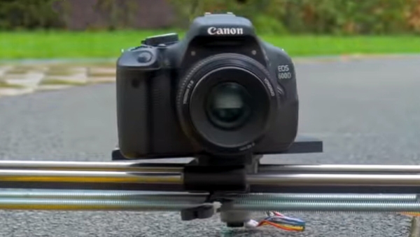
In this day and age, where all leisure activities must be duly captured and monetized online, camera sliders are hot items. Many start with a simple manual build, before graduating to something motorized for more flexibility. [Saral Tayal] took things a step further, implementing a basic tracking mode for even sweeter shots.
The build is mechanically simple, relying on 8mm steel rods and linear bearings more typically found in 3D printers. An Arduino Uno is pressed into service to run the show, outfitted with an OLED screen to run the interface. A RoboClaw motor controller is used to control the geared DC motors used, one controlling the linear motion, the other the rotation of the camera.
With encoders fitted to the motors, the RoboClaw controller enables the Arduino to track the position and rotation of the slider as it moves. The slider then can be given the position of an object relative to itself. With a little maths, it will rotate the camera to track the object as it moves along.
It’s a simple addition to the typical slider build that greatly increases the variety of shots that can be achieved. There are plenty of ways to go about building a slider, too, as we’ve seen before. Video after the break.
Source: OBJECT TRACKING CAMERA SLIDER GETS THE NICE SHOTS
- What components are used for the mechanical structure?
The build relies on 8mm steel rods and linear bearings typically found in 3D printers. - How is the system controlled?
An Arduino Uno runs the interface and controls the entire system. - What hardware manages the motors?
A RoboClaw motor controller is used to control the geared DC motors. - How does the slider track moving objects?
Encoders fitted to the motors enable the controller to track position and rotation so the camera can rotate to follow an object. - What display is used for the interface?
An OLED screen is outfitted to run the interface. - How many motors are required for this build?
Two geared DC motors are used, one for linear motion and one for camera rotation. - Does this project require complex mechanics?
No, the build is described as mechanically simple. - What capability does adding encoders provide?
It allows the Arduino to know the position of the slider and the object relative to itself to calculate necessary rotation.
