Summary of Introduction to the Arduino Project: An Open Source Experimental Aircraft PFD Manual
The Open Cockpit Arduino 4.3 Version 1.0 Beta (Airduino) is an experimental Arduino-based Primary Flight Display for experimental aircraft, intended for education, development, and as an inexpensive backup. This beta guide covers hardware assembly, pitot/static sensor enclosures, wiring (BMP280 sensors, AHRS, level shifter, power switch, rotary encoder), case construction, software installation via the Arduino IDE, configuration via define statements, and ARHS calibration. It emphasizes experimental status, safety disclaimers, BSD 3-Clause licensing, and that certified use is prohibited.
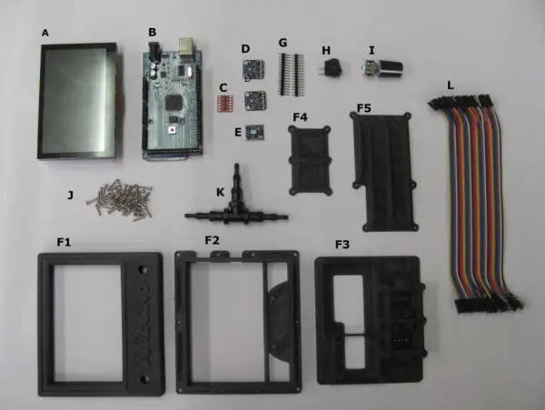
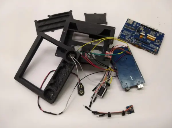
Parts used in the Airduino:
- Arduino MEGA 2560
- Yost Labs AHRS board
- Adafruit BMP280 pressure sensors (two units)
- Logic level shifter (bidirectional)
- Multi-select rotary encoder with momentary NO pushbutton
- Power switch
- 9-volt battery connector (or 6–12V input)
- Shielded twisted pair wire (recommended for AHRS serial)
- Disconnect plug or connector (aviation/automotive style recommended)
- ABS printed case components (pieces 1, 2, 3, 4, 6 and pressure chamber parts)
- Tee-piece tubing for pitot and static ports
- Solder, hookup wires (red, green, yellow, black, orange, brown, gray)
- Heat shrink tubing
- Silicone sealant
- Screws for pressure chamber lid
- Step drill (for fitting holes)
- ABS/plumbing adhesive (Oatey cement recommended)
The Open Cockpit Arduino 4.3 Version 1.0 Beta
The Arduino project is a PFD (Primary Flight Display) for experimental aircraft, built on Arduino’s open-source platform. Its purpose extends to both educational and experimental contexts. Further enhancements are anticipated, aiming to provide an affordable backup instrument for experimental aircraft. This guide outlines the assembly process and software details for the 1.0 beta version.
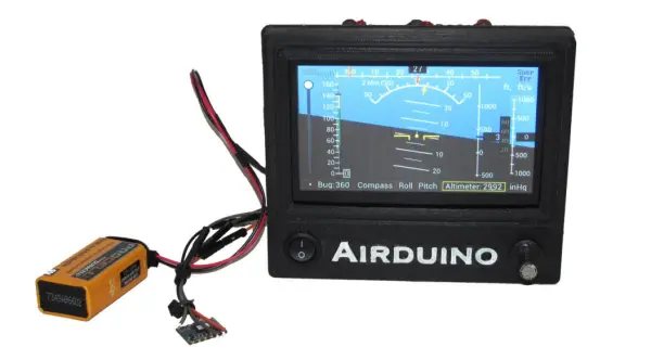
The image depicted above illustrates the second iteration of Airduino, featuring the Yost Labs AHRS system and powered by a 9-volt battery.
Current Release Status: The project is currently in its Beta Release phase. While you’re encouraged to explore and experiment with it, please note that it hasn’t yet attained the level of reliability required for public use.
Cautions and Disclaimers: Flying an aircraft inherently carries risks, and these risks are further magnified when piloting an experimental aircraft. The complexity grows when dealing with experimental avionics on such an aircraft.
The experimental PFD detailed in this guide is decidedly experimental. It should solely be employed in flyable aircraft for the purpose of advancing its development or as a contingency in case primary systems malfunction. In either scenario, conventional non-experimental redundant systems must be integrated into any aircraft hosting an Airduino. These systems should be considered more dependable than the Airduino. In instances where conflicting information arises between the Airduino and the alternative systems, precedence should be given to the other systems for accuracy, considering the Airduino as less reliable.
The Airduino remains in the experimental phase and must not find a place in certified aircraft.
Responsibility for the operation of any Airduino device rests solely upon the operator. Under no circumstances shall the creators of the Airduino assume any liability.
License: This software is licensed under the BSD 3 Clause license as follows:
You are allowed to redistribute and use this in both source and binary forms, whether modified or unmodified, as long as you adhere to the following conditions:
- When redistributing source code, you must preserve the original copyright notice, maintain this set of conditions, and include the subsequent disclaimer.
- When redistributing the software in binary form, it is essential to replicate the initial copyright notice, uphold this set of conditions, and incorporate the subsequent disclaimer within the accompanying documentation or other related materials.
- Utilization of the names of the copyright holder or its contributors to endorse or advertise products originating from this software requires explicit written authorization in advance.
The COPYRIGHT HOLDERS AND CONTRIBUTORS provide this SOFTWARE “AS IS,” and hereby disclaim any express or implied warranties, including but not limited to warranties of merchantability and fitness for a particular purpose. Under no circumstances shall the COPYRIGHT HOLDER OR CONTRIBUTORS be liable for any direct, indirect, incidental, special, exemplary, or consequential damages, including but not limited to procurement of substitute goods or services, loss of use, data, or profits, or business interruption. This holds true regardless of the cause, whether contractual, strict liability, or tort (including negligence or any other theory of liability), arising from the utilization of this SOFTWARE. Even if alerted to the potential for such damages, the user acknowledges the risk and use of this SOFTWARE.
Hardware Assembly:
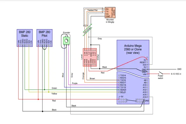
Electrical Schematic
Case Parts:
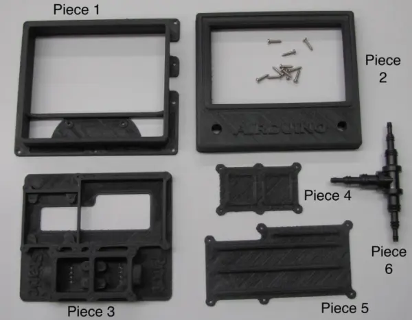
Step 1: Adhere Case Components 1, 3, and 6 to Each Other
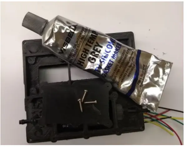
The case was divided into multiple segments during printing to reduce the reliance on supports and mitigate resultant uneven surfaces. Ideally, ABS plastic would have been the printing material of choice. Assembling these segments involves the use of ABS glue. It is advisable to opt for a versatile plumbing adhesive that encompasses ABS. The Oatley cement featured in the subsequent image has proven highly effective for this purpose.
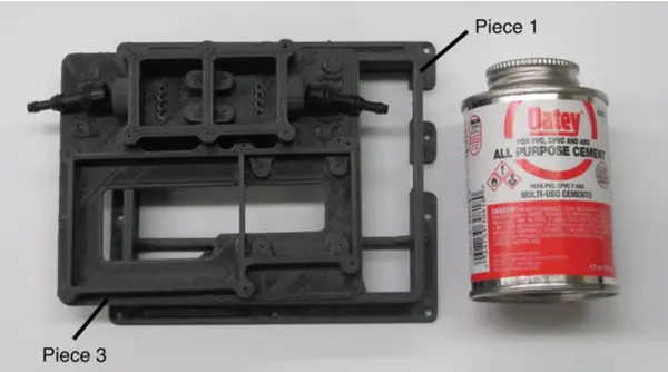
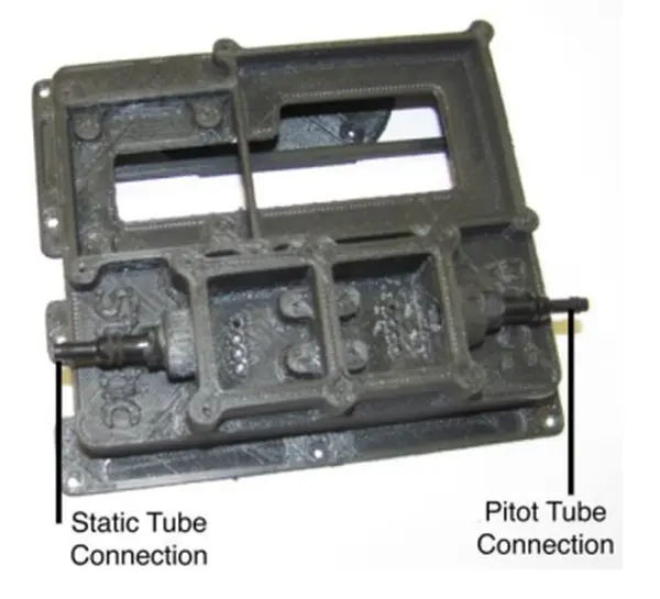
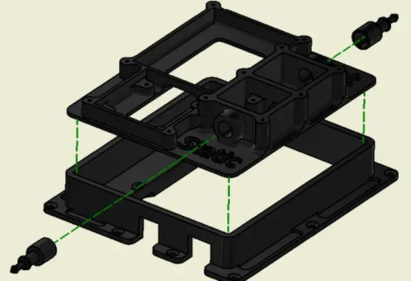
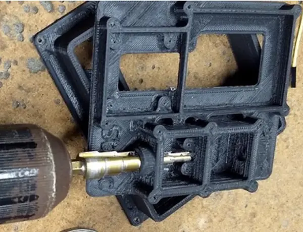
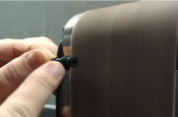
Utilize the adhesive to connect the case components as described earlier. Initiate the process by eliminating the support material from the Pitot and Static port openings, demonstrated below. We’ve found that using a step drill is effective in refining the plastic surface before applying the glue. Following this, trim two ends from Tee-piece 6. These trimmed ends require meticulous sanding for proper insertion into the pitot and static port openings. Once they fit snugly within the openings, they are prepared for the adhesive bonding step. Take care not to make them excessively loose, as this may lead to improper sealing. Applying too much pressure during the press fit could result in delamination of the case layers.
Proceed by adhering piece 3 onto piece 1, following the visual references provided in the photographs and diagrams. The plumbing adhesive tends to cure rapidly.
Step 2: Attach wires to the BMP-280 sensors
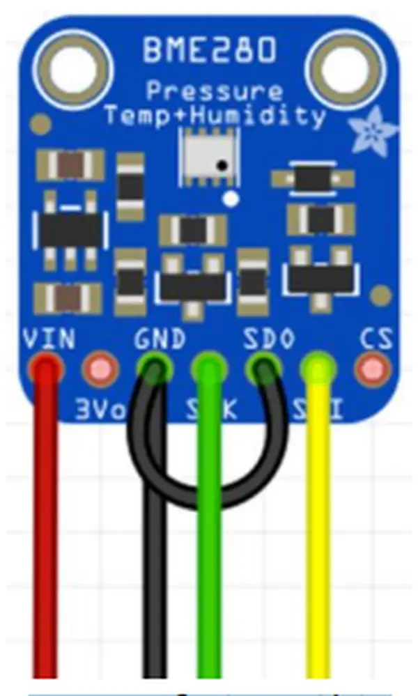
The Adafruit BMP280 sensors come equipped with integrated logic level shifting. Identical sensors are employed for both the Pitot and the Static functionalities. The sole distinction lies in an extra jumper wire connecting GND and SDO on the Static Sensor. This jumper modifies the I2C address on the chip, enabling independent querying by the Arduino for each sensor.
When employing the jumper wires outlined in the materials list, detach the ends from each wire required. Proceed to solder the Red, Green, Yellow, and Black wires onto their respective sensors, following the indicated configuration.
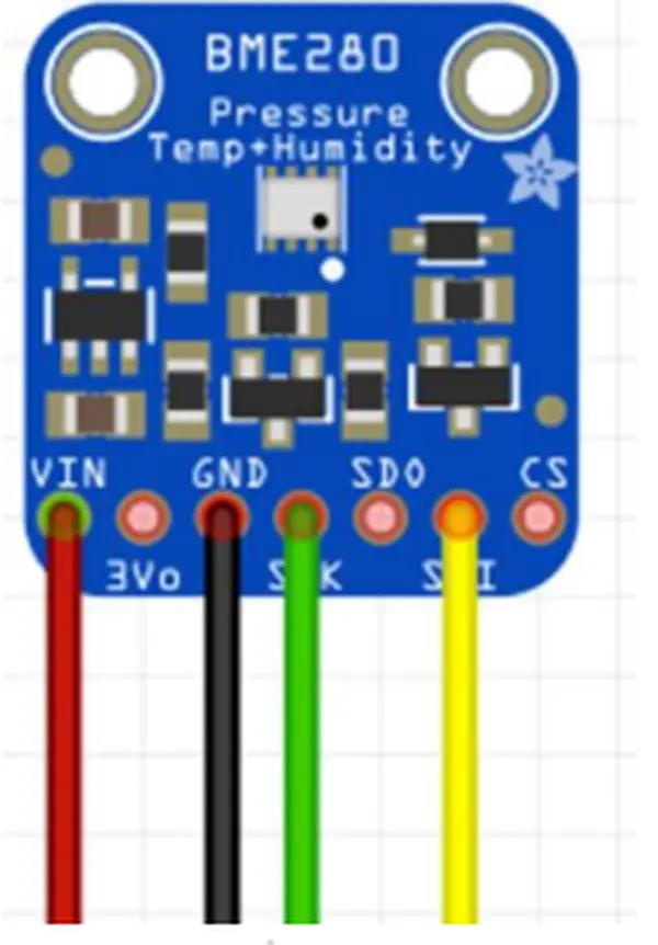
Take note that the wires are soldered onto the pads positioned at the rear of the chips. This arrangement permits the chips to be affixed within the pressure compartments located within the case.
Step 3: Install the Pitot/Static Boards in their Compartments
Both the Pitot and Static BMP-280 sensors need to be enclosed within sealed compartments to effectively detect pitot and static pressure while on the aircraft. These measurements are crucial for calculating airspeed, vertical speed, and altitude. As the instrument’s capabilities expand, these readings will play a vital role in various other calculations.
To commence, initiate the process by drilling the eight wire holes (four for each chamber) using a small drill bit slightly larger than the wires. These holes have been designed into the printed case, though their size may not be precisely suitable.
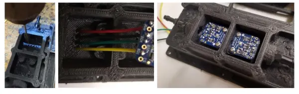
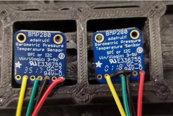
Thread all four wires from the BMP-280 boards through the designated holes in the specified sequence. Keep in mind that the Pitot board includes an additional jumper. Ensuring the accurate alignment of chips with their respective compartments is essential. Finally, carefully fasten the breakout boards onto the designated pads, following the depicted configuration.
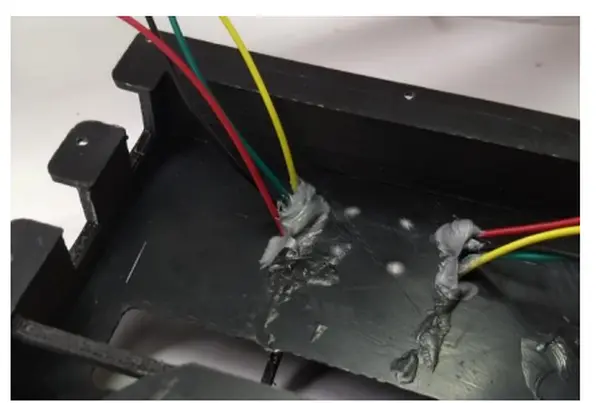
Once the breakout boards are securely fastened, employ silicone sealant to effectively seal the wire connections on the rear side of the case. Begin by pulling the wires to a single side, applying sealant, and then repeating the process in the opposite direction. Although the pressure differentials across the case are minimal, achieving an airtight seal is crucial.
Subsequent to sealing the wires, you can further utilize the same silicone sealant along with screws to seal the lid of the pressure chamber (Piece 4 in the initial diagram) onto the top. Apply a generous amount of sealant, erring on the side of caution. However, be cautious not to overapply sealant to the extent that it might obstruct the pressure sensors on the breakout boards beneath. Any potential leaks in this area can be exceptionally challenging to diagnose, yet they can impede the dependable operation of the pitot-static system.
Step 4: Wire up the Power Switch and Multi-Select Knob
Start by installing the multi-select knob and power switch onto the front of the case (Piece 2). It’s probable that you’ll need to adjust the hole sizes in the printed case to accommodate these components. We discovered that a step drill proved effective for this purpose.
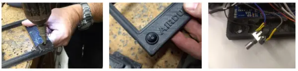
We opted to solder wires onto the power switch while it was positioned within the case, while we performed the soldering for the multi-selector outside the case. Elaboration on the power switch is unnecessary, as a red wire connecting it to the V-in pin’s rear pad on the Arduino suffices. The opposite side will extend out from the case, serving as a connection to a 6-12 volt input voltage.
The multi-selector presents a slightly more intricate design. It incorporates a rotary encoder alongside a momentary NO pushbutton switch. Connecting to the common pin is a ground line, while three data lines are directed back to the Arduino.
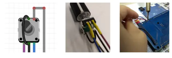
For the ground line, we opted for black, utilizing it to lower the data pins on the Arduino. The black wire is connected to the central pin of the encoder side (which has 3 pins) and then linked to either of the pushbutton side’s pins (which has 2 pins). We omitted the use of heat shrink on the ground wires. The remaining wires were fastened according to the provided illustration, with heat shrink tubing applied to safeguard against any potential signal shorts to ground. All four wires are directed to the solder pads on the rear side of the Arduino, corresponding to the appropriate pins.
Step 5 – Wire in the Logic Level Shifter and the ARHS Board
The Yost Labs ARHS board functions on a 3.3-volt voltage, whereas the Arduino MEGA operates at 5 volts. Consequently, employing a logic level shifter is imperative to prevent potential board damage. Our objective is to situate the AHRS board in a magnetically neutral site, like a wingtip, through remote mounting. For the transmission of high-speed serial data between the Arduino and AHRS, it is advisable to utilize shielded twisted pair wire. Furthermore, it is strongly recommended to incorporate a suitable disconnect plug. While we have not specified a particular plug, we suggest considering a high-quality aviation or automotive-style connector.
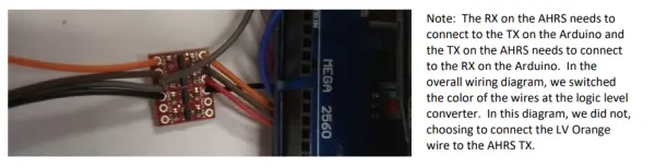
The logic level converter is equipped with two channels, yet only one will be put into use. Specifically, we’ve designated orange and brown wires for UART serial communication. These data wires are soldered to establish a connection between the High Voltage side of the breakout board and the Arduino. Additionally, a black ground wire is employed between the board and the Arduino. This ground wire is further extended to the ground on the LV side of the breakout board (not depicted, located behind the board), continuing onward to the disconnect plug (also not shown). All wires connected to the Arduino are secured to the rear solder pads.
The Arduino board is equipped with an integrated 3.3 Volt power supply, which will serve to energize the AHRS. A gray wire has been employed to establish a connection between the LV side of the board and the 3V3 pin located on the rear of the Arduino. Subsequently, this wire extends onwards to the disconnect plug (unillustrated).
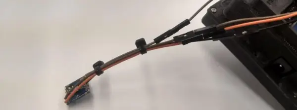
Given that our demo board was not intended for installation in an actual aircraft, we forwent the use of a twisted wire pair or a high-grade disconnect mechanism. Instead, we utilized simple male/female wire ends for our disconnection setup. This arrangement sufficed for our experimental purposes, yet it falls considerably short when employed in any form of testing apparatus.
To ensure comprehensive functionality, it’s advisable to consider incorporating a protective housing for the AHRS board. Additionally, it might be prudent to include an extra disconnect plug at this end as an added measure.
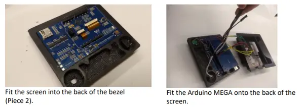
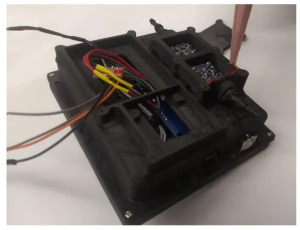
Step 6: Putting it all together.
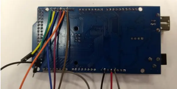
Now, it’s the appropriate juncture to assemble all the components. The image above presents the current configuration, featuring the power wire linked to a 9-volt battery connector. Your setup might vary in appearance based on your selected voltage source.
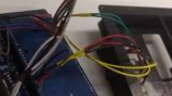
Combine the two yellow wires from the Pitot and Static breakouts into a single yellow wire, which then connects to the indicated pin on the Arduino. Repeat this process for the two green, two red, and two black wires. Refer to the illustration below. Pay attention to the heat shrink tubing used to cover the soldered connections.
Download and Installation:
Numerous steps within this section are contingent upon your computer’s operating system. While the following instructions pertain to a Windows-based system, the same procedures can be carried out on a Linux or Mac computer by referring to instructions available on Arduino forums. This process was effective as of April 2019. Should any changes have occurred on the website or software, kindly refer to the updated instructions provided on the respective platform.
1. Acquire the Arduino IDE by downloading and installing it on your computer.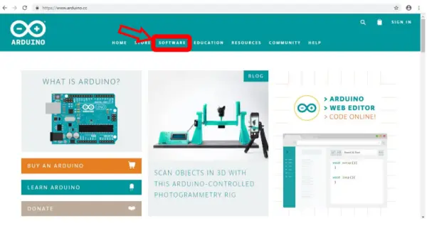
- Navigate to Arduino.cc, access the software section, and choose the “Downloads” option.
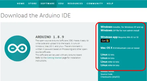
- Choose the suitable version of the Arduino IDE (Integrated Development Environment). Proceed to click on the chosen version, which should initiate the download process.
- Launch the file and grant it permission to install on your computer. The default settings should be suitable.
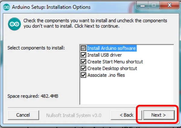
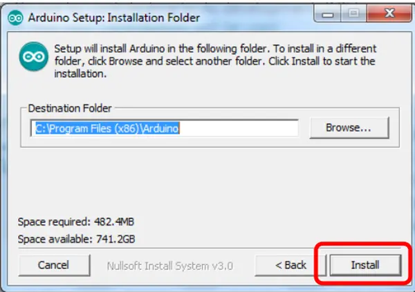
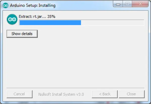
- You might need to provide the program with authorization to install multiple files and drivers. Please wait until the IDE completes the installation process.
2. Incorporate the four essential libraries into Arduino.
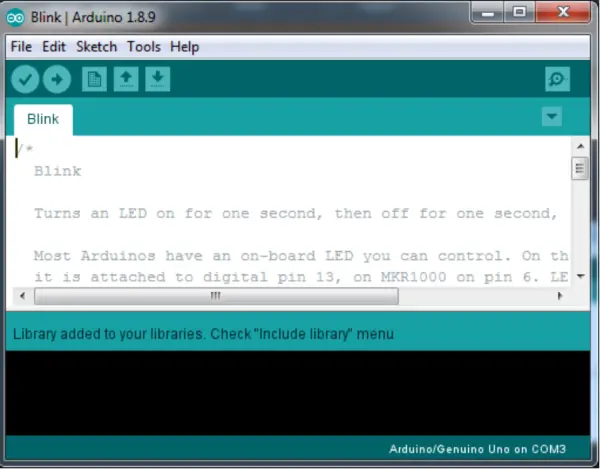
- Open the Arduino IDE.
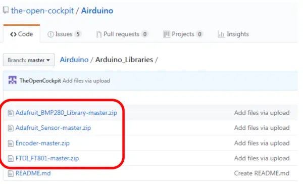
- Retrieve the four zip files from the Arduino_Libraries directory on GitHub. Ensure you are aware of the storage location on your computer where you save these files. Keep them in their zipped format without extracting them.
- Return to the Arduino IDE, navigate to “Sketch,” then proceed to “Include Library,” and finally select “Add .Zip Library.”
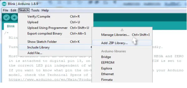
- This action will prompt a window to appear, allowing you to browse to the location where you stored the four libraries. Choose one of the libraries, and the software should proceed to install it for you. The image below demonstrates the appearance of a successful installation on my computer.
- Repeat the process outlined in steps “F” and “G” until all four libraries have been successfully installed.
3. Launch the Airduino program within your Arduino IDE.
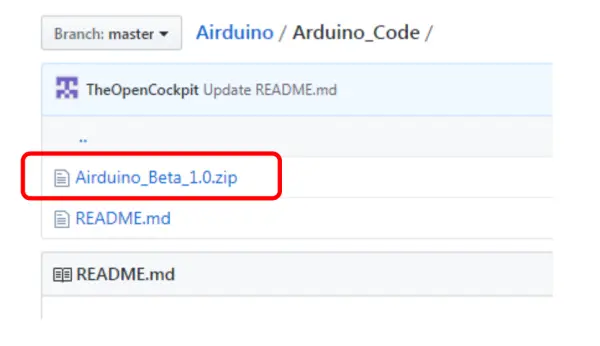
- Obtain the Airduino code from GitHub and make a note of the location where you save it. Unlike before, you should unzip the downloaded file this time.
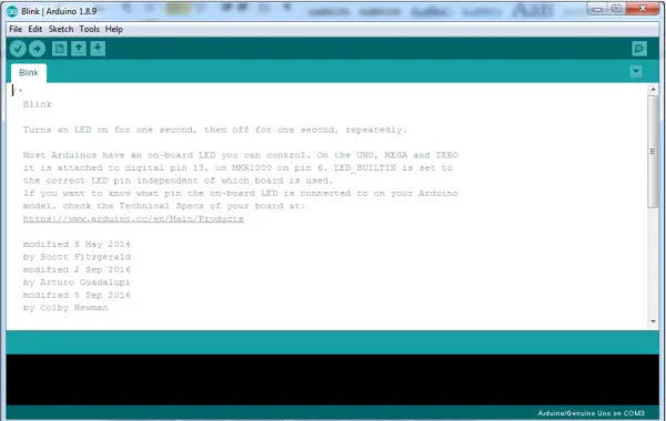
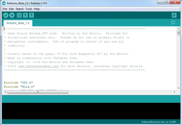
- Within the Arduino IDE, select “File” followed by “Open.” Navigate to the directory where you extracted the folder in the previous step, and open the relevant file. If the process is successful, you should observe the following:
- Change the board type to “MEGA 2560,” which corresponds to the specific board utilized in the Airduino. Access the “Tools” menu, proceed to “Board,” and then choose “Arduino/Genuino Mega or Mega 2560.” (Please be aware that if you’ve employed a MEGA 2560 board from a different brand, you might need to select an alternative board setting.)
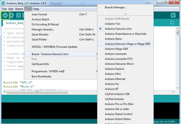
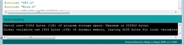
- Ultimately, verify your setup by clicking on the Check Mark icon located in the upper left corner of the program interface (as illustrated in the image above within the green box). If your installation is accurate, you will observe text appearing within the lower black box. This process may require a brief duration, but you should receive the following output:
4. Transfer the program to the Airduino unit that you have constructed.
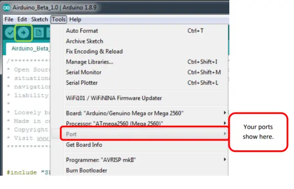
- Choose the suitable port from the “Tools” menu, specifically the “Port” option highlighted in red below.
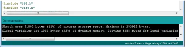
- Select the “Upload” button indicated in green below.
- The program compilation, similar to previous instances, will require some time before proceeding to upload it onto the board. Upon successful execution, you will witness a display resembling the example provided below. Your Airduino unit will momentarily power off and subsequently restart, presenting the lower screen.
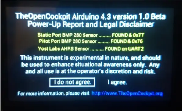
Kindly observe that agreeing to the disclaimer is necessary to proceed. Rotate the multi-select knob and press “I agree.” If you encounter difficulty while selecting the “I agree” option, it might be necessary to adjust the setting for “#define ECPD 2 // number of encoder clicks per detent. Probably 1, 2, or 4,” as explained in the upcoming section. Additionally, please take note that if either of the static port BMP 280 sensors or the Yost Labs AHRS sensor is not detected, they will appear in red. This situation typically indicates a wiring error.
5. Set up the software configuration using the provided define statements explained in the following section. Once you’ve adjusted the software configuration within the Arduino IDE, you will be required to perform another software upload, as described in section 4.
Software Configuration:
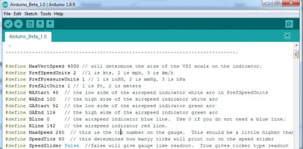
In keeping with standard Arduino practices, the initial code section employs define statements to specify the desired options. Modify the numeric values associated with each option accordingly. For true/false settings, input “true” or “false” in lowercase letters. If the term is recognized, the color will change as depicted below next to “SpeedSlider.”
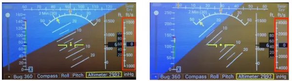
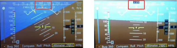
1. Utilize #define MaxVertSpeed to set the upper and lower limits of the displayed VSI (Vertical Speed Indicator) scale. You are free to choose any desired numerical value. The example provided illustrates 1000 below on the left and 4000 displayed both above and below on the right.
2. Assign #define BLine as 74 to designate the position of the blue line on the airspeed indicator. If a blue line is not required, use 0.

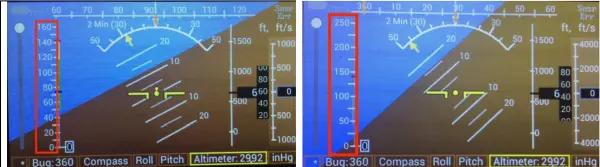
3. Use #define MaxSpeed to set the upper limit displayed on the gauge. Opt for a value slightly higher than your red line. For instance, 160 and 250 are shown below.
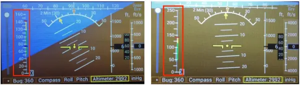
4. Set #define SpeedTics to determine the spacing between numbers on the speed slider. While any value can be selected, it’s advisable to choose a sensible figure. The default is 20, with 50 also being a recommended option.
5. Utilize #define BottomWhiteArc to specify the lower boundary of the white arc.
6. Set #define TopWhiteArc to determine the upper limit of the white arc.
7. Employ #define BottomGreenArc to designate the lower extent of the green arc.
8. Employ #define TopGreenArc to establish the upper limit of the green arc and the lower limit of the yellow arc.
9. Utilize #define RedLine to specify the upper limit of the yellow arc and define the red line.
10. Adjust #define HeadingNum as either true or false to display the heading within a black box at the center of the Directional Gyro strip.
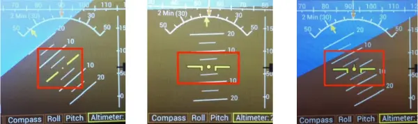
11. Modify #define CenterDisplayType to 3, offering a choice between different display options: 1 presents yellow lines with the horizon, 2 maintains level yellow lines, and 3 combines both features.
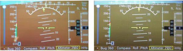
12. Adjust #define dynamicsky as either true or false. Enabling true results in display color changes based on pitch, while selecting false maintains a static display color.
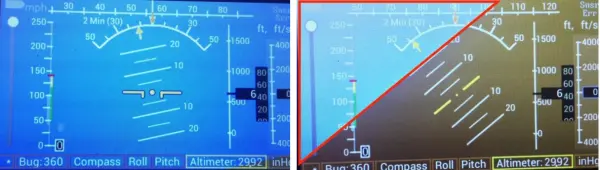
13. Set #define dynamicground as either true or false. Enabling true causes display color changes based on pitch, while choosing false maintains a static display color.
Sensor Calibration:
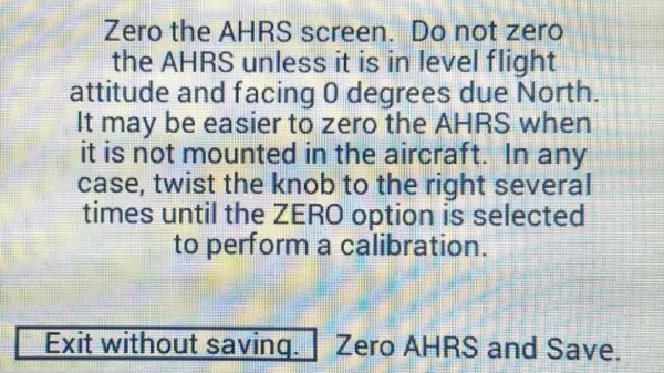
This screen allows you to reset the ARHS chip to its current position. Presently, it doesn’t retain the newly set zero position once the power is turned off, although this feature will be incorporated in the future. To access this screen, power off the unit, then hold down the selector knob while turning on the power. As soon as this screen emerges, release the knob. To navigate the cursor to “Zero AHRS and Save,” rotate the knob in that direction for several turns. Subsequently, press the select knob to execute the zeroing process.
- What is the Airduino intended for?
The Airduino is an experimental Arduino-based Primary Flight Display for education, development, and as an affordable backup instrument for experimental aircraft. - Can Airduino be used in certified aircraft?
No. The Airduino is experimental and must not be used in certified aircraft. - How are the pitot and static BMP280 sensors differentiated?
The static sensor has an extra jumper connecting GND and SDO to change its I2C address so the Arduino can query each sensor independently. - How should the AHRS be connected to the Arduino?
Use a logic level shifter for UART serial (orange and brown wires) plus a ground, power the AHRS from the Arduino 3.3V pin, and use shielded twisted pair and a disconnect plug for remote mounting. - What adhesive and material are recommended for the printed case?
ABS plastic is preferred for printing and an ABS/plumbing adhesive such as Oatey cement is recommended to join case segments. - How are the BMP280 breakout boards installed and sealed?
Solder wires to rear pads, thread wires through drilled holes into sealed pressure compartments, fasten boards to pads, and seal wire entries and chamber lid with silicone sealant. - How do you upload the Airduino software?
Install the Arduino IDE, add the four required libraries via Add .Zip Library, open the Airduino code, set board to MEGA 2560, select the port, and click Upload. - How are display options configured in software?
Configure display behavior using define statements at the start of the code (e.g., MaxVertSpeed, MaxSpeed, arcs, HeadingNum, CenterDisplayType, dynamicsky, dynamicground) and re-upload the sketch. - How do you zero the AHRS sensor?
With power off, hold the selector knob while powering on, release when the calibration screen appears, rotate to Zero AHRS and Save, then press the knob to zero. - What indicates a sensor or AHRS is not detected?
If a static BMP280 or the Yost Labs AHRS sensor is not detected it will appear in red on the display, typically indicating a wiring error.