Summary of Recommended Approach to Programming and Hardware Development: C++ and Arduino Framework
Rapid Overview of the Seed Studio Grove Kit: The Seed Studio Grove Kit pairs an Arduino-compatible Seeeduino Lotus board with integrated Grove sensors and actuators on a high-quality PCB, enabling safe, plug-and-play hardware prototyping. The kit includes examples (LED blink, Mega Demo, meteo station) and instructions to install drivers, Arduino IDE, libraries (U8g2), and upload demos like the grovebk4a Mega Demo and a DHT-based temperature/humidity OLED display.
Parts used in the Seed Studio Grove Kit:
- Grove - LED: Simple
- Grove - Buzzer: Piezo Buzzer
- Grove - OLED Display 0.96": 128x64
- Grove - Button: Momentary Push Button
- Grove - Rotary Potentiometer: Adjustable Potentiometer
- Grove - Light sensor
- Grove - Sound sensor
- Grove - Temp & Humi Sensor (DHT11)
- Grove - Air Pressure Sensor (BMP280)
- Grove - 3 Axis Accelerator (LIS3DHTR)
- Seeeduino Lotus (Arduino compatible board with Grove ports)
- Grove cables
Story
Rapid Overview of the Seed Studio Grove Kit
Frequently, people inquire about the optimal approach to delve into programming and hardware development. The response consistently points to the C++ language and, notably, the Arduino framework.
While the software aspect is well-defined, what about the hardware dimension? The solution lies in the Seed Studio Grove Kit. This comprehensive kit offers an avenue to enter the realm of Arduino programming, enabling the creation of intricate projects that harness advanced sensors and streamline connectivity with diverse hardware components, all adhering to the Grove standard. This approach safeguards against potential short circuits and mitigates the risk of hardware component damage.
Within this assessment, we shall establish the Arduino environment and employ the Mega Demo to showcase the board’s full array of functions. Simply adhere to the provided instructions and embark on a coding journey filled with satisfaction.
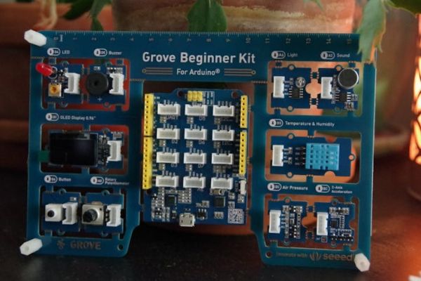
The Hardware
Crafted upon a superior-grade PCB, the kit boasts remarkable build quality. Each sensor and component interfaces with the board through an Arduino-based microcontroller. This design ensures that, within the code, one can effortlessly access the sensors and actuators without necessitating any physical connections, thanks to the comprehensive integration facilitated by the fundamental PCB.
In this context, there exists the option to detach individual components for potential reuse in personalized projects. However, I recommend refraining from detaching components from the PCB initially, and instead, commence code testing using the default PCB.
The components are as follows:
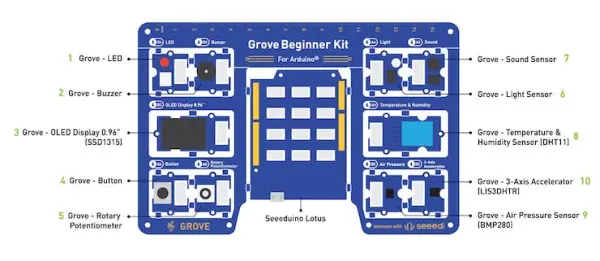
1. Grove – LED: Simple
2. Grove – Buzzer: Piezo Buzzer
3. Grove – OLED Display 0.96″: 128×64 dot resolution High brightness, self-smission and high contrast ratio
4. Grove – Button: Momentary Push Btton
5. Grove – Rotary Potentiometer: Adjustable Potentiometer
6. Grove – Light: Detects surrounding light intensity
7. Grove – Sound: Detects surrounding sound intensity
8. Grove – Temp%Humi Sensor: Detects surrounding temperature and humidity values
9. Grove – Air Pressure Sensor: Detect surrounding atmospheric pressure
10. Grove – 3 Axis Accelerator: Detects object acceleration
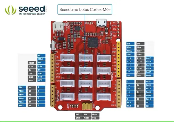
11. Seeeduino Lotus: Arduino Compatible Board with Grove Ports
Ports:
1. LED || Digital || D4
2. Buzzer || Digital || D5
3. OLED || I2C || I2C, 0x78 (default)
4. Button || Digital || D6
5. Potentiometer || Analog || A0
6. Light || Analog || A6
7. Sound || Analog || A2
8. Temp & Humi || Digital || D3
9. Air Pressure || I2C || I2C, 0x77 (default) / 0x76 (optional)
10. Accelerator || I2C || I2C, 0x19 (default)
A. The Software
1. Install the driver
First af all you need the USB driver comunication. Download the driver in accord with your OS by using this link https://www.silabs.com/developers/usb-to-uart-bridge-vcp-drivers
2. Install the Arduino IDE
Retrieve and install the latest iteration of the Arduino IDE by accessing this provided link.https://www.arduino.cc/en/software
3. Upload the cod
3.1 Launch the Arduino IDE on your personal computer. Navigate to Tools -> Board -> Arduino AVR Boards -> Arduino Uno to appropriately designate the desired Development Board Model. Opt for Arduino Uno as the chosen board.
3.2 Access Tools -> Port to designate the accurate Port (which corresponds to the Serial Port identified in the Device Manager during the prior step). In this instance, COM11 is the designated option. For those using Mac OS, the designation should be /dev/cu.SLAB_USBtoUART.
3.3 Duplicate and insert the subsequent code snippet into the Arduino IDE.
// Projectg code for Seeed Studio January 2022
// The LED will turn on for one second and then turn off for half second
int ledPin = 4; //declare the pin for the led
void setup() {
pinMode(ledPin, OUTPUT); //define the pin 4 as an output
}
void loop() {
digitalWrite(ledPin, HIGH); //switch ON the PIN number 4 so the Led connect
delay(500); //delay for 500 millisecond
digitalWrite(ledPin, LOW); //switch OFF the PIN number 4
delay(500); // delay for 500 millisecond
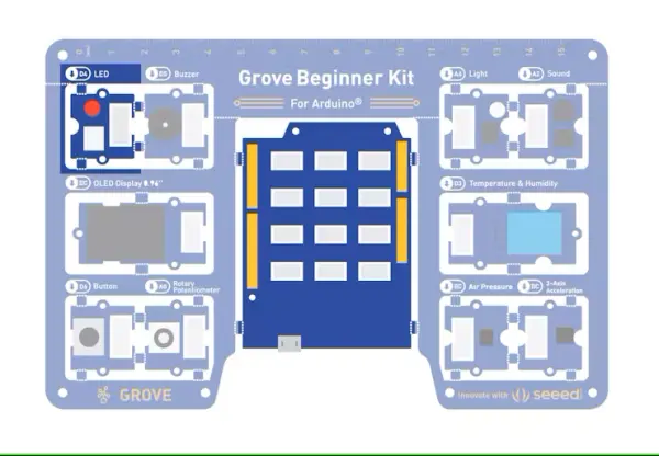
} B. The Hardware 1. Seeeduino Lotus
2. Grove LED
3. Grove Cable (If Broken out)
The full MEGA demo
Utilize this demonstration to showcase the complete array of features within the kit and explore the comprehensive management of its components. The detailed guide can be found at the following link: https://github.com/jpralves/grove-beginner-kit-for-arduino
1. Install the u8g2 library on the Arduino IDE
The initial approach we will examine involves the library manager, accessible by going to Sketch > Include Library > Manage Libraries.
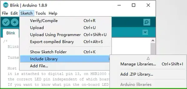
From this point, we have the capability to search for frequently employed libraries and allow the IDE to handle their automatic download and installation. In our scenario, we will install a U8g2 library to facilitate the connection between our Arduino and a U8g2 device. To initiate this, begin by searching for “U8g2” within the upper-right box and patiently await the appearance of results in the window.
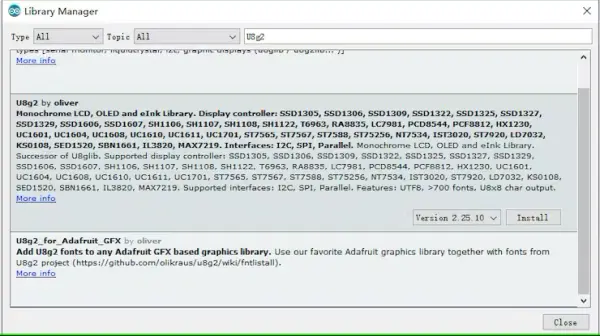
Choose the library and proceed by clicking the “Install” button.
As the installation transpires, you will observe changes in the lower progress bar, accompanied by status messages like “Downloading”.
2.Download the Grovebk4a Mega Demo
Following the successful installation of the library, acquire the Grovebk4aMegaDemo authored by Joao Alves at [email protected]. The most recent iterations can be accessed from both https://jpralves.net and https://github.com/jpralves/grove-beginner-kit-for-arduino.
Within this compilation, you’ll encounter an array of 10 distinct demonstrations:
-
- logoShow.ino coupled with buzzerShow.ino: A fusion of the OLED display module and the buzzer module.
- cubeShow.ino: Presents a 3D rotating cube through the OLED display module.
- microShow.ino: Offers three distinct displays of an audio spectrum analyzer using the Grove microphone module.
- tempShow.ino: Exhibits temperature and humidity readings via the DHT11 module.
- pressureShow.ino: Displays pressure and temperature readings using the BMP280 module.
- aceleShow.ino: Depicts x, y, z accelerations employing the LIS3DHTR module.
- lightShow.ino: Showcases values from the light sensor module.
- trimShow.ino: Utilizes a gauge to display the value of the trimmer module.
The selection of demos can be alternated by pressing the button on the Grove Kit.
A brief examination of the code snippets within the grovebk4a-mega-demo.ino file has the potential to alter the various demonstration scenarios.
oid loop() {
if (digitalRead(buttonPin) == HIGH) {
while (digitalRead(buttonPin) == HIGH) delay(10);
stateMode = (stateMode + 1) % (sizeof(funcShow)/sizeof(funcShow[0]));
}
funcShow[stateMode]();
}
&logoShow, &cubeShow, µShow1, µShow2, µShow3, &tempShow, &pressureShow, &aceleShow, &lightShow, &trimShowMeteo Station Project
Within this undertaking, the board retrieves temperature and humidity data from the DHT sensor, subsequently showcasing the outcomes on the OLED display.
The utilization of the U8g2 library is mandatory, and it’s imperative to include all the files from the provided zip package. To begin, download the zip package from this tutorial, extract its contents, and open them within the Arduino IDE. Proceed to upload the code and observe the outcomes. This exclusively represents the annotated “main” code segment.
// Include all the library

#include <U8g2lib.h>

#include "DHT.h"
// declare the pins and setup the components
const byte dhtPin = 3;
DHT dht(dhtPin, DHT11);
U8G2_SSD1306_128X64_NONAME_1_HW_I2C u8g2(U8G2_R2, /* reset=*/U8X8_PIN_NONE);
// setup the serial for the debug and the OLED display
void setup() {
Serial.begin(115200); //setup the serial port
u8g2.begin(); //setup the oled
}
// start the loop
void loop() {
const int col = 20;
int humid = dht.readHumidity(); //read the humidity
int temp = dht.readTemperature(); //read the temperature
u8g2.firstPage();
do {
u8g2.setFont(u8g2_font_t0_16b_mr);
u8g2.setCursor(col, 16);
u8g2.print(F(“temp: “));
u8g2.print(temp);
u8g2.print(F(“C”));
u8g2.setCursor(col, 48);
u8g2.print(F(“humid: “));
u8g2.print(humid);
u8g2.print(F(“%”));
u8g2.drawLine(10, 0, 10, 64);
} while(u8g2.nextPage());
}
Extra contents about the main board
The “deep dive” on Seeed Studio Lotus Cortex-M0+
- Fully compatible with Arduino UNO
- ARM® Cortex®-M0+ 32bit 48MHz microcontroller(SAMD21)
- 12 on-board Grove connectors
- 14 Digital I/O Pins (10 PWM outputs)
- 6 Analog Inputs
- Support Power Path Management
- Support micro-usb or Li-Po battery powered
- 2A maximum charging current
- Suitable for low power design
Notable Details Regarding UART, Battery, and Serial Functionality
Grove UART: Offers 3 hardware UART ports, including 1 dedicated Grove UART. The TX-RX pins are available in the header, alongside the multiplexed function pin SCKSDO in the SWD port.
Serial Port: The Serial interface corresponds to the Grove UART, while Serial1 corresponds to the RX-TX connection in the header region.
Li-Po Header: Seeduino Lotus Cortex-M0+ provides the flexibility to be powered by either a USB connection or a Li-Po battery. Furthermore, the board facilitates Li-Po battery charging. When simultaneously powered through USB and the Li-Po battery, the battery will undergo charging, signaled by the flashing CHR LED. Upon the battery reaching full charge, the CHR LED ceases to flash.
- How do I install the USB driver for the Seeeduino Lotus?
Download the USB to UART VCP driver from https://www.silabs.com/developers/usb-to-uart-bridge-vcp-drivers as instructed in the article. - How do I set the Arduino board type for uploading code?
In the Arduino IDE go to Tools -> Board -> Arduino AVR Boards -> Arduino Uno and select Arduino Uno as described. - How do I select the correct serial port for uploading?
Open Tools -> Port and choose the COM port shown in Device Manager (example COM11) or /dev/cu.SLAB_USBtoUART on Mac, per the article. - How can I run the basic LED blink example?
Copy the provided LED blink code into the Arduino IDE, set pin 4 as output, then upload with the board and port configured as instructed. - How do I install the U8g2 library required for the OLED demos?
Use Sketch -> Include Library -> Manage Libraries, search for U8g2 and click Install as shown in the article. - Where can I get the Grovebk4a Mega Demo examples?
Download the Grovebk4a Mega Demo by Joao Alves from https://jpralves.net or https://github.com/jpralves/grove-beginner-kit-for-arduino as stated. - How do I switch between demos on the Mega Demo?
Press the button on the Grove Kit to cycle through the demo functions as described in the demo loop code. - Does the meteo station use a specific sensor and display library?
Yes, it reads DHT11 temperature and humidity and uses the U8g2 library to display values on the OLED, per the article. - Can components be detached from the PCB for reuse?
Yes, components can be detached for reuse, but the article recommends first testing code with the default PCB in place. - What power options does the Seeeduino Lotus Cortex-M0+ support?
It supports micro-USB or Li-Po battery power and provides Li-Po charging and power path management as noted in the article.