Washing should be done even without the presence of the COVID-19 pandemic. Appropriate washing can prevent the transmission of diarrheal infections and other person-to-person illnesses.
For personal health, it is quite useful to follow CDC guidelines on hand washing whenever one returns from being out of your house.
Below are the some of the CDC guidelines regarding washing your hands.
“How Germs Spread
Washing hands can keep you healthy and prevent the spread of respiratory and diarrheal infections from one person to the next. Germs can spread from other people or surfaces when you: Touch your eyes, nose, and mouth with unwashed hands. Prepare or eat food and drinks with unwashed hands. Touch a contaminated surface or objects, Blow your nose, cough, or sneeze into hands and then touch other people’s hands or common objects.
Key Times to Wash Hands: You can help yourself and your loved ones stay healthy by washing your hands often, especially during these key times when you are likely to get and spread germs: Before, during, and after preparing food. Before eating food. Before and after caring for someone at home who is sick with vomiting or diarrhea. Before and after treating a cut or wound. After using the toilet. After changing diapers or cleaning up a child who has used the toilet. After blowing your nose, coughing, or sneezing. After touching an animal, animal feed, or animal waste. After handling pet food or pet treats. After touching garbage. During the COVID-19 pandemic, you should also clean hands: After you have been in a public place and touched an item or surface that may be frequently touched by other people, such as door handles, tables, gas pumps, shopping carts, or electronic cashier registers/screens, etc. Before touching your eyes, nose, or mouth because that’s how germs enter our bodies.
Follow Five Steps to Wash Your Hands the Right Way. Washing your hands is easy, and it’s one of the most effective ways to prevent the spread of germs. Clean hands can stop germs from spreading from one person to another and throughout an entire community—from your home and workplace to childcare facilities and hospitals. Follow these five steps every time. Wet your hands with clean, running water (warm or cold), turn off the tap, and apply soap. Lather your hands by rubbing them together with the soap. Lather the backs of your hands, between your fingers, and under your nails. Scrub your hands for at least 20 seconds. Need a timer? [Author: Use this Instructable.] … Rinse your hands well under clean running water. Dry your hands using a clean towel or air dry them.”
This Instructable hopes to insure we wash our hands in keeping with CDC guidlines. The CDC recommends that we wash our hands for at least twenty (20) seconds, at the key times stated above. This Instuctable lights LEDs at five (5) second intervals, that allow us to see the time from five (5) seconds to sixty (60) seconds. It helps identify when twenty (20) seconds have past, and it continues to provide timing information, up to sixty (60) seconds should we chose to wash longer than the minimal, twenty (20) seconds, CDC recommendation.
There are a number of Instructables that have been published to assist Makers to follow CDC hand washing guidelines. However, I believe this is the easiest to build and has the greatest time range.
It is also simple to construct and fun to use.
Supplies
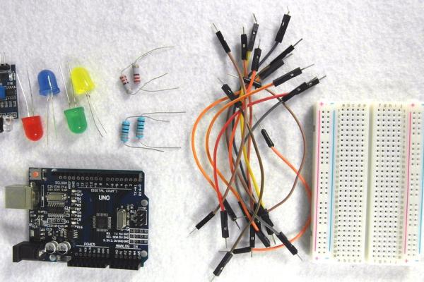
The supplies needed for this project are,
– An Arduino UNO
– A small breadboard
– An IR Obstacle Avoidance Module
– Four (4) LEDs. ( I used four (4) different colored 10 mm LEDs here, but 3mm, 5mm, or 8mm LEDs will work as well, and the LEDs need not be different colors.) Note: the voltage specifications of LEDs change with their size and color. For the 10mm LEDs I used here, these are,
Yellow: 1.8 – 2.2 (VDC)
Green: 2.8 – 3.0 (VDC)
Blue: 2.8 – 3.0 (VDC)
Red: 1.8 – 2.2 (VDC)
Although the actual current depends on the size and color of the LED and the value of the current-limiting resistor, the current in each LED circuit is approximately 20ma.
– Four (4) resistors. (I used two (2) 220 ohm and two (2) 330 ohm resistors in this Instructable, as noted above the resistance of LEDs change with their size and color, and I wanted to insure all LEDs were easy to see. I used 1 watt resistors here, but any resistor with a rating of 1/4 watt of greater should work.)
– Dupont Male-to-Male cables to connect components.
I also used an experimental platform, to make it easier to move the assembly as a unit. Fortunately an experimental platform is not needed, although it may prove helpful.
Step 1: Test Obstacle Avoidance Module
Before we connect all components together it will be useful to test that the IR Obstacle Avoidance Module and the four (4) LEDs are working correctly.
The IR Obstacle Avoidance Module is tested in this Step and the LEDs are tested in the next Step.
In this Step we want to insure the Obstacle Avoidance Module is working correctly before we use it in our project.
The IR Obstacle Avoidance Module outputs a LOW or zero (0) when an obstacle (a hand in this Instructable) is near, and we test for this LOW signal.
By using this Module it will not be necessary to physically touch any component to start the timer. Fortunately, testing this module is quite easy to do, as the Sketch below shows.
The IR Obstacle Avoidance Module used here comes with three pins, as can be seen in the attached photograph. The pins are labeled OUT, GND, and VCC, The GND pin on the Module connects to any ground header on the UNO. The VCC pin connects to 5 volts on the UNO, and the OUT pin is connected here to digital header four (4) on the UNO board.
The Sketch shown below is also shown in an attached text file, possibly in a better format.
/*
Test IR Obstacle Avoidance Module
Written May 25, 2020
by R Jordan Keindler
*/
int IRAvoidance = 4;
int val;
void setup() {
pinMode(IRAvoidance, INPUT);
Serial.begin(9600);
}
void loop() {
val = digitalRead(IRAvoidance);
if (val == 0)
{
Serial.print(“Hand Near\n”);
}
}
Step 2:
Step 3: Test Four (4) LEDs
In the previous Step we tested the IR Obstacle Avoidance Module. We wrote a Sketch for this test and ran it.
In this step we test the four (4) LEDs and also the four (4) attached resistors. Fortunately, we do not need to write a sketch. We can test the LEDs and resistors directly using headers on the UNO.
We connect the positive side of each LEDs to one side of a resistor. For the Yellow and Green LEDs we use 220 ohm resistors. For the Blue and Red LEDs we use 330 ohm resistors. The other side of each resistor goes to the positive rail on a breadboard.
We use values of the resistors that are different to allow all LEDs to be easily seen.
The negative side of each LED goes to the negative rail of the breadboard.
The positive rail get its 5 volts from the 5V header on an Arduino UNO, and the ground rail on the breadboard is connected to a GND header on the UNO.
All connections are shown in the attached pictures.
The attached video shows that all LEDs and resistors work. As shown in that video all LEDs are turned on, directly from the Arduino UNO, so they are all working as are their associated resistors. The configuration shown here allows a complete circuit for each LED, between ground and 5 volts.
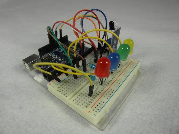
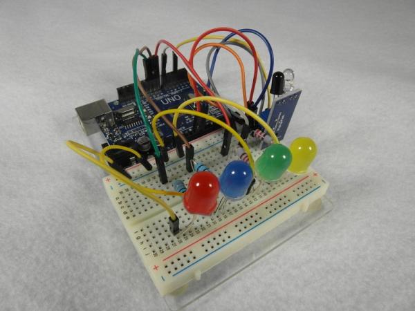
Step 4: Build the Unit-Combine the IR Obstacle Avoidance Module, LEDs, and Resistors
We use the IR Obstacle Avoidance Module to let us know when a hand is close and thus start the timer. We do not need to touch any component for the timer to start.
To have the Arduino-based assembly let us know the time that has past we add four (4) LEDs and their current limiting resistors. We use different colored 10mm LEDs. In this example, we use Yellow, Green, Blue, and Red LEDs,
The completed assembly including IR Obstacle Avoidance Module, LEDs, and resistors is shown in the attached pictures.
The Sketch that is used to detect if a hand is close and run the timer is shown in the next Step.
The positive side of each of the four (4) LEDs is connected to one side of a resistor. For the Yellow and Green LEDs this is a 220 ohm resistor. For the Blue and Red LEDs this is a 330 ohm resistor. Different value resistors are used to insure that all LEDs are easily seen.
The other side of each resistor is connected, respectively, to Arduino UNO digital headers 7, 8, 9, and 10.
The negative side of each of the four (4) LEDs is connected to a ground rail on a breadboard. The ground rail is in turn connected to a GND header on an Arduino UNO. This allows each LED, as appropriate, to have a complete circuit between ground and 5 volts.
Step 5: The Sketch to Make the Timer Work
Below you will find the Sketch to run the assembly. This Sketch is also attached as a text file, which may have a slightly improved format.
In the setup function, first the IR collision Avoidance Module is set for input and then the four (4) LEDs are set for output.
The value OUT for the IR Collusion Sensor Module is then read. If this value equals zero (0), we know that a hand is nearby. If so, this starts the first of three (3) cycles and begins the timer. The Sketch turns the first LED On, and in turn, the second, third, and fourth LEDs. It than does the same two (2) times more.
When the timer finishes the first of its three (3) cycles, immediately before the Yellow LED is again On, and we begin the second (2nd) cycle, the Red LED is On, if we wait until the Yellow LED is again On, over twenty (20) seconds have past, i.e., if we take the RED LED’s On state to the end, before turning the Yellow LED On this is twenty (20) seconds, – the minimum CDC guideline for washing hands. That is, when the Yellow LED begins cycle two over twenty (20) seconds have past.
The Sketch goes on for two (2) more cycles, for a total time of 60 seconds.
After the Sketch completes all three (3) cycles it then waits until a hand is again near to once more begin its timing.
/*
Wash Hands Timer
Written May 25, 2020
by R Jordan Keindler
Turns on four (4) LEDs in turn for approximately
five (5) seconds each. When the last of the four LEDs is on, twenty (20)
seconds has past. The sketch cycles three (3) times in the loop() function. That is,
three times each for all four (4) LEDs. Thus, time is measured, utilizing the four (4)
LEDs, as approximately 5, 10, 15, 20 || 25, 30, 35, 40 || 45, 50, 55, and 60 seconds. That is
5-20 seconds in cycle one, 25-40 seconds in cycle 2, and 45-60 seconds in cycle 3.
When the last cycle is complete sixty (60) seconds will have past.
This implementation uses two (2) 220 ohm resistors, and two (2) 330 ohm resistors,
four (4) 10mm LEDs, and an IR collision avoidance sensor.
*/
int IRAvoidance = 4; // Assign the IR Obstacle avoidance Sensor to digital header 4
int val; // Set val as an integer
int led1 = 7; // Assign the first LED to digital header 7
int led2 = 8; // Assign the second LED to digital header 8
int led3 = 9; // Assign the third LED to digital header 9
int led4 = 10; // Assign the fourth LED to digital header 10
int delay1 = 5000; // Set delay before the next LED is turned On
void setup() {
pinMode(IRAvoidance, INPUT); // Set the IR Collision Sensor for input.
pinMode(led1, OUTPUT); // Set the first LED for output.
pinMode(led2, OUTPUT); // Set the second LED for output.
pinMode(led3, OUTPUT); // Set the third LED for output.
pinMode(led4, OUTPUT); // Set the fourth LED for output.
}
void loop() {
val = digitalRead(IRAvoidance); // Read the IR Collision Avoidance OUT pin
if (val == 0) // If a hand is near start for loop
{
for (int i = 1; i <= 3; i++) /
{
digitalWrite(led1, HIGH); // Turn the first LED On
digitalWrite(led2, LOW); //Turn the other LEDs Off
digitalWrite(led3, LOW); // “
digitalWrite(led4, LOW); // “
delay(delay1); // Wait Approximately five (5) seconds before turning On the next LED
digitalWrite(led2, HIGH); // Turn the second LED On
digitalWrite(led1, LOW); //Turn the other LEDs Off
digitalWrite(led3, LOW); // “
digitalWrite(led4, LOW); // “
delay(delay1); // Wait Approximately five (5) seconds before turning On the next LED
digitalWrite(led3, HIGH); // Turn the third LED On
digitalWrite(led1, LOW); //Turn the other LEDs Off
digitalWrite(led2, LOW); // “
digitalWrite(led4, LOW); // “
delay(delay1); // Wait Approximately five (5) seconds before turning On the next LED
digitalWrite(led4, HIGH); // Turn the fourth LED On
digitalWrite(led3, LOW); //Turn the other LEDs Off
digitalWrite(led2, LOW); // “
digitalWrite(led1, LOW); // “
delay(delay1); // Wait Approximately five (5) seconds before turning On the next LED
digitalWrite(led1, LOW); // Turn all LEDs Off
digitalWrite(led2, LOW); // “
digitalWrite(led3, LOW); // “
digitalWrite(led4, LOW); // “
}
}
}
Source: Non-Contact Hand Washing With LED Timer Displays