
Summary of Neo Pixel, Fastest Thumb Game.
This project is a competitive schoolyard game built for Makerfaire, where players race to light a NeoPixel ring by pressing buttons. The winner receives a green flashing ring, while the loser gets red. Constructed using SolidWorks for 3D printing and Fritzing for circuit design, the device uses an Adafruit Trinket microcontroller and an Ethernet cable for handsets. The build process involves milling custom PCBs, soldering components, and assembling the physical casing.
Parts used in the Thumb Game:
- Solder headers female and male
- Adafruit Trinket - Mini Microcontroller - 5V Logic
- NeoPixel ring
- 3 x AAA Battery Holder with On/Off Switch and 2-Pin JST
- 2 x 10K resistors
- An old Ethernet network cable
- JST-PH 2-Pin SMT Right Angle Connector
- Screw Terminals 2.54mm Pitch (3-Pin) and (5-pin)
I built this project because to take to my local Makerfaire In Newcastle, UK. The idea was to make a school yard game that would be relatively cheap and simple to produce.
The idea is simple, to win you have to press the button repeatedly until you fill the pixel ring with light. You compete directly with an opponent and the winner gets a green flashing ring, whilst the loser gets a red flashing ring.
To make the project, I used SolidWorks design, 3D printing and I designed the circuit boards using Fritzing. I had the circuit boards milled My University.
In all I think the project turned out well. The video shows game play; simple but effective.
Step 1: Parts Required
I had some of this stuff lying around but it shouldn’t cost too much to build the whole thing. I used an ethernet data cable for the handsets because it had plenty of cores to wire the handsets and buttons.
Parts List:
Solder headers female and male
Adafruit Trinket – Mini Microcontroller – 5V Logic
3 x AAA Battery Holder with On/Off Switch and 2-Pin JST
2 x 10K resistors
an old Ethernet network cable
JST-PH 2-Pin SMT Right Angle Connector
Screw Terminals 2.54mm Pitch (3-Pin) and (5-pin)
Step 2: The Circuit Board
The first iteration was obviously built on a bread board but once I had done that, I designed the circuit board using Fritzing. I did the whole thing in the circuit board view because I wanted to use headers, rather than components on the breadboard, to plug things in. This way also allowed me to use screw terminals for the handsets.
I have uploaded the .fzz file, I am not sure how much use the schematic is ,but you can easily use the file to get the board milled or etched.
The board view shows the underside of a single sided board. I have labelled the screw terminals with the relevant wires form the handsets.
Step 3: The Handsets
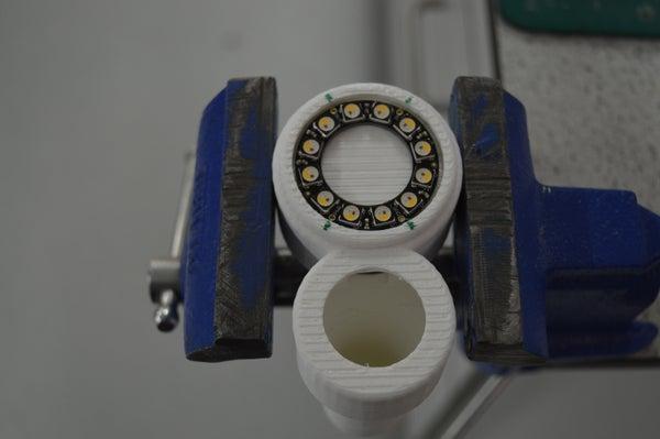
The SolidWorks file and the STL file for the handsets are included.
I used a Makerbot to print them and they were oriented standing straight up as (i.e the way you hold them). I forgot to allow holes for the wires of the Neo-pixel rings so I had to drill them.
I marked the positions of the holes with a marker pen and I used a hand drill to drill the holes.
Step 4: Wiring the Handsets
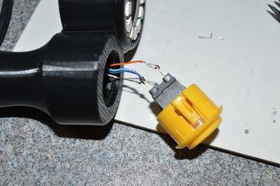
This was a bit tricky, but after tinning the wires, I found that by inserting the data cable first and using a small screwdriver to tease the wires into the right position I was able to pass the wires through the drilled wholes and the button hole.
The wire colors for my data cable were wired like this
NeoPixel Ring
——————————————————-
Brown – NeoPixel In
Brown and White -NeoPixel Out
Green – Neopixel Power
Green and White- Ground
——————————————————-
Button
——————————————————-
Blue – Button Ground
Blue and white- Button Signal
I wired the these two to the same button terminal
Orange Button 5V
Step 5: Soldering the Circuit Board
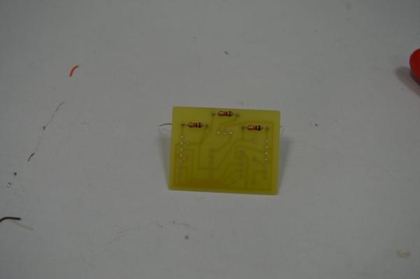
I did the building in a few stages:
1) I soldered the battery connector to the Trinket.
This is surface mount soldering so a little tricky but found the a bulldog clip was useful to hold the connector in place for soldering.
2) I soldered in the jumpers and the resistors.
There are three in the circuit and I realized later that two are not required. Also I had originally intended to use a reset button, but found that the battery pack on off switch as a reset was better and easier to program. (maybe version 2 will be better)
3) then I soldered the screw terminal in place.
4) finally I soldered in the trinket
Source: Neo Pixel, Fastest Thumb Game.
- What is the main goal of the game?
To win you have to press the button repeatedly until you fill the pixel ring with light. - How do you determine the winner?
The winner gets a green flashing ring, whilst the loser gets a red flashing ring. - Can I use this project without spending much money?
The idea was to make a game that would be relatively cheap and simple to produce. - What software was used to design the circuit board?
I designed the circuit boards using Fritzing. - Which tool was used to print the handsets?
I used a Makerbot to print them. - What type of cable connects the handsets?
I used an ethernet data cable because it had plenty of cores to wire the handsets and buttons. - Did all the resistors need to be soldered?
I realized later that two of the three resistors are not required. - What was used to hold the connector in place during soldering?
A bulldog clip was useful to hold the connector in place for soldering.
