Summary of MSP430 FET using TI Launchpad
This article describes a cost-effective In-System Programming (ISP) solution for Texas Instruments MSP430 MCUs using the MSP430 Launchpad as a Flash Emulator Tool. It enables Spy-By-Wire programming and serial communication but is limited to 3.6V operation, making it unsuitable for boards operating outside this voltage range without additional level shifting.
Parts used in the MSP430 FET Project:
- Texas Instruments MSP430 Launchpad
- Flash Emulator Tool (FET)
- J3 connector
- Five jumpers from J3
In order to do In System Programming (ISP) you usually need a Flash Emulator Tool (FET). For the Texas instruments MSP340 family you can buy the one that TI sells for their MCUs:
That costs about 100$ and it isn’t too much if you program MCUs for a living. It can work with supplies from 1.8V to 3.6V and do program/debug using JTAG or Spy-By-Wire (2 Wire) interfaces.
For the hacker that buys their own tools there are cheaper solutions. You can find several references on Internet about people that have used the MSP430 Launchpad to do ISP programming. This Launchpad board is designed to program MSP430 MCUs of the “G” value line in dip packages using an included 20 pin socket. As all the signals needed to do Spy-By-Wire are available so you can use this board to program MCUs located in another board as long as you route the needed signals: TDIO, TCK and the reference GND to the proper pins of the MCU to program.
This article explains a FET implementation using the TI Launchpad. As this board provides also a serial TX/RX communication using the PC USB connection. It will also be implemented in the FET.
Features
- Two Wire Spy-By-Wire for the MSP430 family
- Serial TX and RX communication at 3.6V level
Limitations and Disclaimer
The FET will inherit all the limitations related to the use of the TI Launchpad as a FET device.
- Can only use Spy-By-Wire, no full JTAG is available
- It can only work with and provide 3.6V
The second limitation could be important. As the Launchpad works at a fixed 3.6V supply, the provided Vcc and the signaling is at 3.6V. As long as the board you communicate with is at about 3.6V all will be ok.
As 3.6V is the maximum operating voltage in the MSP430 you cannot connect the FET to a board that operates the MCU at a greater voltage. In the case of connecting to a board that uses a lower voltage, let’s say 2.5V, you could power the board without using the FET, but the signaling from the FET to the board will be at 3.6V and that could be above the Absolute Maximum Ratings from the MCU. Adding level shifters is out of the goals of this project so I recommend using this FET only when the board is powered between 3.3V and 3.6V in order to guarantee that the Maximum Ratings are not exceeded.
If the connected board should work at less than 3.3V I recommend to power it at 3.6V from the FET during the programming and debugging and powering it at it’s own lower voltage when it is disconnected from the FET.
Off course this document is only a documentation of something I have done for myself and there are no provided guarantees that it will suit your own needs or that it won’t blow-up your home. Yoy have been warned.
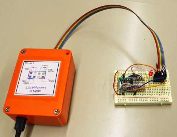
Launchpad Signals and project schematic
The signals needed to program a MSP430 chip and provide Serial communication are mainly at the J3 connector that links the emulator upper side of the board with the target MCU lower side. As we won’t use the lower part, we will take out all the five jumpers in J3.
For more detail: MSP430 FET using TI Launchpad
- How can I program MSP430 MCUs cheaply?
You can use the TI MSP430 Launchpad board to implement a Flash Emulator Tool instead of buying the official expensive tool. - What interfaces does the official TI Flash Emulator support?
The official tool supports JTAG and Spy-By-Wire interfaces with supplies ranging from 1.8V to 3.6V. - Does this project support full JTAG programming?
No, this implementation only supports Two Wire Spy-By-Wire and does not provide full JTAG capabilities. - Can I use this FET with a board powered at 2.5V?
No, you should not connect it directly because the 3.6V signaling exceeds the absolute maximum ratings of a 2.5V MCU. - What is the recommended voltage range for the target board?
The target board must be powered between 3.3V and 3.6V to ensure signal levels do not exceed maximum ratings. - How do I handle boards that operate below 3.3V?
You can power the board at 3.6V from the FET during programming and switch to its own lower voltage when disconnected. - Which signals are required for Spy-By-Wire programming?
The necessary signals are TDIO, TCK, and the reference GND routed to the proper pins of the target MCU. - What extra feature does the Launchpad provide besides programming?
The Launchpad also provides serial TX and RX communication via the PC USB connection at 3.6V levels.