Summary of ITTT || ARDUINO-UNO || ANTIPONG CONSOLE
This article details the creation of an "Anti-Pong" game console using an Arduino Uno. Unlike traditional Pong, players must dodge a bouncing ball to survive. The project involves designing a custom 3D-printed case, soldering electronic components onto a PCB, and writing custom code to manage gameplay on an OLED display. The author highlights the challenges of coding for limited hardware and the process of refining the physical build through sanding and painting.
Parts used in the Anti-Pong Console:
- Arduino Uno (rev.3)
- Adafruit SSD1306 OLED Display
- Standard PushButtons (3x)
- Piezo Buzzer
- LED (Green)
- 220 ohm Resistor
- 3D Printed Case
- Zero pcb/dot pcb (16cm x 10cm)
- Solder Wire
- Flux
- Set of standard jumper wires (flexible tips)
- Breadboard
- USB-B to USB-A Cable
- Standard charging block
This project and instructable were made as part of an assignment at HKU ( University of the Arts Utrecht ), during the module: If This Then That.
In this instructable we’ll be making a small game console that plays an inverted version of pong. In this version of pong you’ll be dodging the balls instead of “ping-ponging” them over to another player, see how long you can last!
Supplies
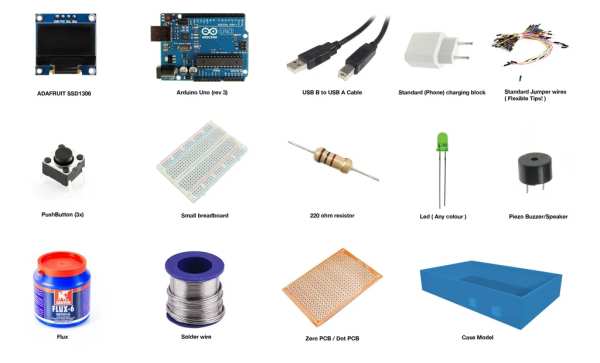
To build this console we’ll be using a bunch of different parts, which can be seen in the image above or the parts list under this sentence, you’ll only need one of each part unless specified otherwise :
// mainboard //
- Arduino uno ( we used rev.3).
// electronic parts //
- Adafruit SSD1306.
- Standard PushButtons – 3x.
- Piezo buzzer.
- Led (any colour, we used green).
- 220 ohm resistor.
// case //
- 3d printed case ( Model link, we made use of a resin printer but a standard filament printer will do fine! ).
- Zero pcb/dot pcb – 16cm x 10cm (6.3 x 3.93 inches).
// testing & soldering //
- Solder wire.
- Flux.
- Set of standard jumper wires (flexible tips!).
- Breadboard (for testing).
// power //
- USB-B to USB-A cable.
- Standard (phone) charging block.
Step 1: Research and Planning
Background:
For the longest time I struggled with what to make for this assignment. Having worked with Arduino’s before but never this substantially and having a hard time limit for when this project should be finished were both important variables to consider.
After doing some digging through other instructables of other creators ( and previous ITTT projects by other students), I found one project that really caught my eye.
The instructable referenced: “ATtiny85 Snake Game”
While I loved this project, I didn’t simply want to recreate what another user already made and decided to give this project my own swing. After speaking with the teachers and other students I quickly decided that instead of snake I would be making a version of the game pong.
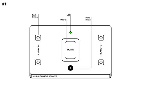
Planning:
In my initial concept I wanted (just like the regular version of pong) to make it a multiplayer experience, where both players had 2 buttons to control the paddle and just ping pong the ball to each other till a person had won. After just a quick bit of googling I found that a lot of other users on instructables had already made an Arduino version of pong (both single and multiplayer) and while for this project I would be allowed to use their code, if altered, I personally wanted to write this code myself.
See “1” for the original concept.
Eventually I decided I would code my own single player version of pong using other projects code as reference, and invert it entirely. Making a pong game where instead of having to hit it, you would have to dodge it and see how long you’re able to survive. Doing this removed the need for another player, and saved a lot of time making and figuring out how to code this.
See “2” for the final concept.
For the assignment the “final product” needs a case and with this final concept reminding me of a Gameboy (which used injection molded cases) this seemed like an excellent time to put a new resin printer I’ve bought to use. While these machines are a bit different than your regular printer the 3d model should work just fine on both.
Step 2: Code
The code for this project turned out to be a lot more difficult than I initially thought it would be. Most components are quite self explanatory but the display worked different from what I imagined. Its not possible to clear an exact part of the screen, instead the entire screen has to be cleared. A workaround I found was to spawn a black object in the spots that should be cleared, which while quirky works great.
While I’m personally not a developer the code (while simple) appears to work flawlessly and doesn’t appear to have any bugs. The limitations of the Arduino-Uno make it so the display’s refresh rate isn’t the highest but the end result is more than playable. Some parts of the code may be redundant or out right unneeded, if there is anything that should be changed feel free to send me a message and I will look at changing the code in this Instructable.
The code for this project can be found below this step and can be uploaded to the Arduino-Uno without any further tweaks.
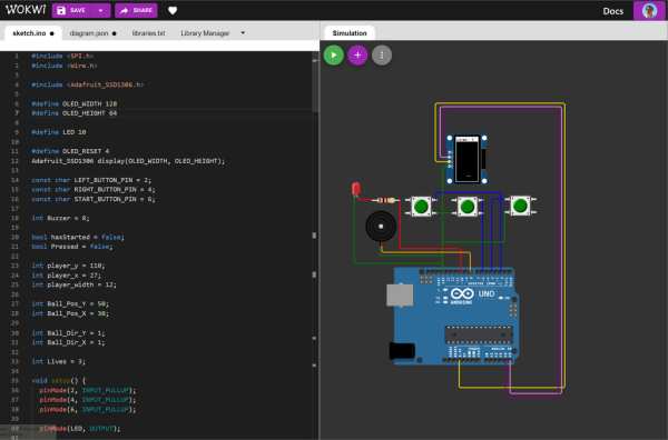
During the testing phase I made use of the online website Wokwi to build my circuit and write my code. There are a bunch of online tools which help you, but Wokwi specifically allowed for the use of the ADAFRUIT SSD1306 which is the display we’re using for this project. See and test the wokwi project here
I did end up testing the final circuit with a breadboard to see if all the parts were working correctly ( I highly recommend doing this before soldering it all together!)
ARDUno_AntiPong.txt
This file contains bidirectional Unicode text that may be interpreted or compiled differently than what appears below. To review, open the file in an editor that reveals hidden Unicode characters. Learn more about bidirectional Unicode characters
Show hidden characters
| #include |
| #include |
| #include |
| #define OLED_WIDTH 128 |
| #define OLED_HEIGHT 64 |
| #define LED 10 |
| #define OLED_RESET 4 |
| Adafruit_SSD1306 display(OLED_WIDTH, OLED_HEIGHT); |
| const char LEFT_BUTTON_PIN = 2; |
| const char RIGHT_BUTTON_PIN = 4; |
| const char START_BUTTON_PIN = 6; |
| int Buzzer = 8; |
| bool hasStarted = false; |
| bool Pressed = false; |
| int player_y = 110; |
| int player_x = 27; |
| int player_width = 12; |
| int Ball_Pos_Y = 50; |
| int Ball_Pos_X = 30; |
| int Ball_Dir_Y = 1; |
| int Ball_Dir_X = 1; |
| int Lives = 3; |
| void setup() { |
| pinMode(2, INPUT_PULLUP); |
| pinMode(4, INPUT_PULLUP); |
| pinMode(6, INPUT_PULLUP); |
| pinMode(LED, OUTPUT); |
| display.begin(SSD1306_SWITCHCAPVCC, 0x3C); // initialize with the I2C addr 0x3C (for the 128×32) |
| display.clearDisplay(); |
| display.display(); |
| Draw_TitleScreen(); |
| } |
| void loop() { |
| digitalWrite(LED, HIGH); |
| bool Current_Left_State = digitalRead(LEFT_BUTTON_PIN); |
| bool Current_Right_State = digitalRead(RIGHT_BUTTON_PIN); |
| bool Current_Start_State = digitalRead(START_BUTTON_PIN); |
| if (Current_Start_State == Pressed && hasStarted == false) { |
| display.clearDisplay(); |
| hasStarted = true; |
| display.drawFastHLine(player_x, player_y, player_width, WHITE); |
| } |
| if (hasStarted) { |
| Draw_Court(); |
| Draw_Lives(); |
| } |
| if (Current_Left_State == Pressed && hasStarted == true && player_x != 5) { |
| player_x -= 2; |
| // Draw player moving left. // |
| display.drawFastHLine(player_x, player_y, player_width, WHITE); |
| display.drawFastHLine(player_x + player_width, player_y, player_width, BLACK); |
| } |
| if (Current_Right_State == Pressed && hasStarted == true && player_x != 47) { |
| player_x += 2; |
| // Draw player moving right. // |
| display.drawFastHLine(player_x, player_y, player_width, WHITE); |
| display.drawFastHLine(player_x – player_width, player_y, player_width, BLACK); |
| } |
| display.drawPixel(Ball_Pos_X, Ball_Pos_Y, WHITE); |
| Draw_Lives(); |
| Ball_Pos_Y += Ball_Dir_Y * 4; |
| Ball_Pos_X += Ball_Dir_X * 4; |
| display.drawPixel(Ball_Pos_X, Ball_Pos_Y, WHITE); |
| display.drawPixel(Ball_Pos_X – Ball_Dir_X * 4, Ball_Pos_Y – Ball_Dir_Y * 4, BLACK); |
| // checks if the ball has hit a vertical wall, and inverts the movement direction. |
| if ( Ball_Pos_X <= 1 || Ball_Pos_X >= 63 ) { |
| Ball_Dir_X = Ball_Dir_X * -1; |
| Sound_Bounce(); |
| } |
| // checks if the ball has hit the ceiling or the player paddle, and inverts the movement direction. |
| if ( Ball_Pos_Y <= 16 || Ball_Pos_Y >= 127) { |
| Ball_Dir_Y = Ball_Dir_Y * -1; |
| Sound_Bounce(); |
| } |
| if ( Ball_Pos_Y == 110 && Ball_Pos_X >= player_x && Ball_Pos_X <= player_x + player_width && hasStarted == true) { |
| Ball_Dir_Y = Ball_Dir_Y * -1; |
| Lives -= 1; |
| Sound_Hit(); |
| } |
| if (Lives == -1) { |
| Game_Over(); |
| } |
| display.display(); |
| } |
| void Draw_TitleScreen() { |
| // rotate display 90 degrees to match physical orientation. // |
| display.setRotation(1); |
| // top bar |
| display.fillRect(0, 0, 64, 14, WHITE); |
| // outline |
| display.drawRect(0, 0, 64, 128, WHITE); |
| display.setTextSize(2); |
| display.setTextColor(WHITE); |
| display.setCursor(4, 20); |
| display.println(“ANTI”); |
| display.setCursor(4, 40); |
| display.println(“PONG”); |
| display.setTextSize(1); |
| display.setTextColor(WHITE); |
| display.setCursor(18, 100); |
| display.println(“Press”); |
| display.setCursor(18, 108); |
| display.println(“Start”); |
| tone(Buzzer, 200); |
| delay(500); |
| noTone(Buzzer); |
| } |
| void Draw_Court() { |
| // top bar |
| display.fillRect(0, 0, 64, 14, WHITE); |
| // outline |
| display.drawRect(0, 0, 64, 128, WHITE); |
| // display.setTextSize(2); |
| // display.setTextColor(WHITE); |
| // display.setCursor(4, 20); |
| // display.println(“Dodge”); |
| // display.setCursor(4, 40); |
| // display.println(“That”); |
| // display.setCursor(4, 60); |
| // display.println(“Ball”); |
| } |
| void Sound_Bounce() |
| { |
| if (hasStarted == true) { |
| tone(Buzzer, 500, 50); |
| } |
| } |
| void Sound_Hit() |
| { |
| if (hasStarted) { |
| tone(Buzzer, 800, 50); |
| } |
| } |
| void Draw_Lives() { |
| display.setTextSize(1); |
| display.setTextColor(BLACK); |
| display.setCursor(3, 5); |
| display.println(“Lives:”); |
| display.setCursor(45, 5); |
| display.println(Lives); |
| } |
| void Game_Over() { |
| display.clearDisplay(); |
| display.drawRect(0, 0, 64, 128, WHITE); |
| display.setTextSize(2); |
| display.setTextColor(WHITE); |
| display.setCursor(4, 10); |
| display.println(“You”); |
| display.setCursor(4, 30); |
| display.println(“Lost”); |
| display.setTextSize(1); |
| display.setTextColor(WHITE); |
| display.setCursor(4, 100); |
| display.println(“Back to”); |
| display.setCursor(4, 108); |
| display.println(“Menu….”); |
| display.display(); |
| display.drawRect(0, 0, 64, 128, WHITE); |
| delay(3000); |
| display.clearDisplay(); |
| Draw_TitleScreen(); |
| hasStarted = false; |
| Lives = 3; |
| } |
Step 3: Circuit
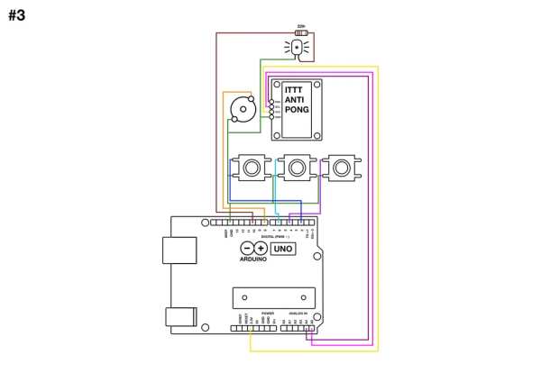
Image of the the circuit for this project. I decided to remake the circuit in photoshop as the digital version wasn’t the best for legibility.
Step 4: Case
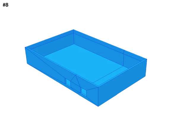
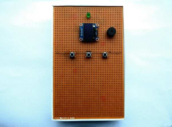
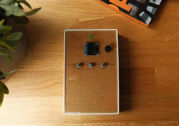
As mentioned earlier I was going to use a resin (SLA) printer to make the case for my project. Initially I had planned to make a top and bottom half of this case but I simply loved how the bare PCB looked, so I ended up scrapping the top portion of the case. As I’m quite inexperienced with cad programs I opted to use the 3d modelling and animation software maya to build my case. While this software is way less precise and makes it harder to get measurements, this case was simple enough to get by with using maya.
See “4” for the model in maya.
After maya I imported the model in the slicer program Chitubox ( which came with the printer ), added supports and sliced it to make it ready for printing.
See “5” for the model in Chitubox.
The print took roughly 7 and a half ours to finish, so I decided to print it overnight to save on the power bill.
After the print finished, I took it out of the printer and saw some of the corners were slightly bend as a likely result of improper supports. Luckily with this being a plastic case, this can be easily remedied with hot air and bending it into shape after it has gotten hot
See “6” for the case straight out of the printer.
after a bit of bending back and some test fitting, the parts fit perfectly together.
See “7” for the result.
Due to the weird refresh rate of the screen the screen appears off on photos, this however is fine in real life.
Step 5: Soldering
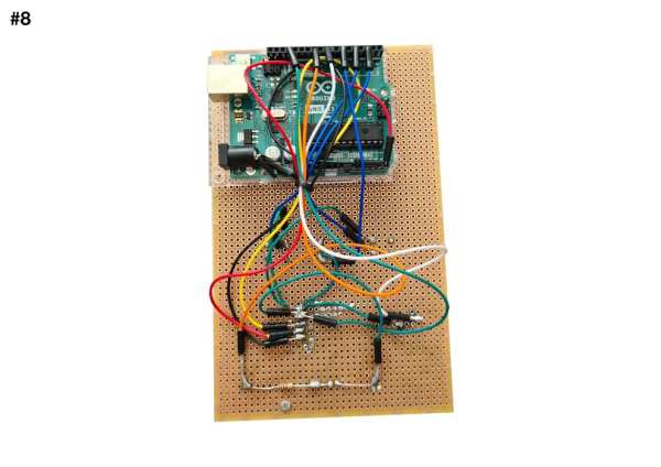
Soldering proved quite a lot more doable than I initially imagined. The screen has a few tiny connectors, but these are fairly well spaced out. The only issue I found was that there are simply not enough ground ports on the Arduino Uno itself, so you’re going to have to be a bit creative. One fortunate thing about the ground wires is, that they can all be soldered together, I soldered all the ground wires together at one central spot, the display, and then looped them back into the ground pin on the board.
In the supplies section I mentioned the importance of jumper wires with bendable tips, if the tips are not bendable the board will simply not fit inside the case and the wires itself will be rather lose in their sockets.
See “8” for the soldering result.
After the soldering is done, first mount the USB-A in the slot closest to the bottom (on the left hand side) so its stuck in place, after that just fit the PCB in place and you’re ready to go.
Step 6: Polishing
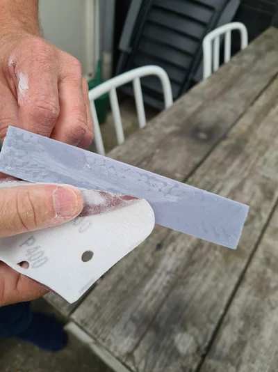
While the case, straight out of printer, looks fairly representable, I personally really wanted it to be white to match the orange PCB. I started with sanding with 400grit sandpaper to roughen up the extremely smooth surface of the printed model and smooth the hard edges, then used primer and eventually white spray-paint to paint the case.
This step is not at all required but makes the case look a lot nicer to hold and look better aesthetically.
// caution //
Even though the model was UV-cured always take safety precautions, there is a lot of really fine resin dust floating around after you sand it. wear a mask.
Step 7: Gameplay
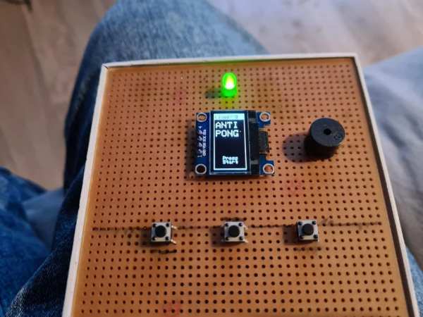
The actual use of the console is fairly self explanatory.
The game prompts the user to press start to start the game, after which the player will have 4 lives ( 0 counts as a life ) to try and survive as long as possible dodging the bouncing ball. The game will end when all lives are lost and will automatically return to the home screen.
There are 3 buttons on the device itself. The middle of the three buttons serves as a start button, and after the game has started the left and right button will be used to control the player paddle ingame.
Step 8: Final Thoughts
This was a super fun project to work on, this isn’t something that normally interests me at all but I’ve learnt a lot of new skills and technics to use on future projects. Furthermore I’m super pleased with the end result, its fairly compact, easy in use and really expandable. I will definitely iterate on this project in the future in one way or another.
Source: ITTT || ARDUINO-UNO || ANTIPONG CONSOLE
- How does the gameplay differ from regular Pong?
Instead of hitting the ball back to a player, you must dodge the ball to see how long you can survive. - What software was used to design the 3D printed case?
The creator used Maya for modeling and Chitubox as the slicer program. - Can I use a standard filament printer instead of a resin printer?
Yes, the article states that a standard filament printer will work fine for the case model. - Why did the author choose to invert the game concept?
Inverting the game removed the need for a second player and saved time on coding multiplayer logic. - What tool helped test the circuit before soldering?
The online website Wokwi was used to build the circuit and write the code during testing. - How many lives does the player start with?
The player starts with 4 lives, where 0 counts as a life. - What is the best way to handle the ground connections on the Arduino Uno?
Solder all ground wires together at one central spot and loop them back into the single ground pin on the board. - Does the entire screen need to be cleared to update the display?
Yes, it is not possible to clear an exact part of the screen; the workaround is to spawn a black object in the spots that should be cleared.