
Summary of Motion Sensing Eye using arduino
This article guides users in building a "Motion Sensing Eye" using an Arduino and a Freetronics Dot Matrix Display (DMD). The project creates an interactive eye graphic that opens when motion is detected by an alarm sensor. The author plans future updates to include Bluetooth and Android connectivity, though these are not yet functional in the current build.
Parts used in the Motion Sensing Eye:
- An Arduino or similar microcontroller
- A Freetronics Dot Matrix Display
- Arduino link cable for DMD
- An alarm motion sensor
- Mini breadboard and jumper cables
- A 10k resistor
- Power supply for the alarm sensor
- USB cable for Arduino
- Arduino Prototype shield (Optional)
- Stackable headers (Optional)
- Wire (Optional)
- Tactile push buttons (Optional)
- Terminal Blocks (Optional)
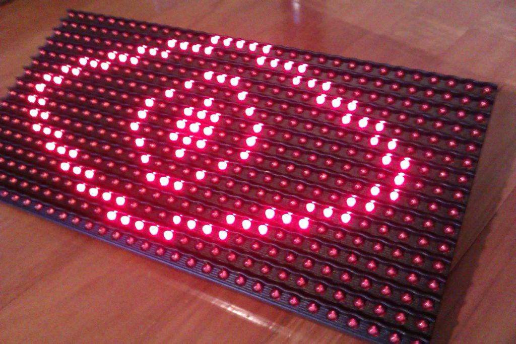
This instructable will hopefully finish with you having a working dmd, that will display an eye that opens if something in a room moves (above in the pictures are some gifs of it in action). This instructable will also be updated with bluetooth and android support in the near future (when I get it working).
Anyway, Let’s Go!
Update (05/02/14):
– added optional shield
Step 1: Materials
Things you will need:
– An Arduino or similar
– A Freetronics Dot Matrix Display
– Arduino link cable for dmd
– An alarm sensor
– Mini breadboard and jumper cables
– A 10k resistor
– Power supply for the alarm sensor
– Usb cable for arduino
Optional:
– Arduino Prototype shield
– Stackable headers
– Wire
– Tactile push buttons
– Terminal Blocks
Coming Soon Eventually:
– Arduino compatible bluetooth module
– bluetooth dongle for PC
– An android phone
Step 2: The Freetronics DMD
The dot matrix display I have used for this project can be found here
It features a 32×16 LED display, giving you a total of 512 high brightness LEDs to play with.
Two extra libraries are needed for the Arduino IDE, and these can be found here and here
You can check that your dmd is functioning properly by running the dmd_demo sketch found in the DMD library you will have just downloaded. Once uploaded to your arduino, connect it and the dmd with the link cable as depicted by the pictures.
Congratulations, your dmd is working correctly
For more detail: Motion Sensing Eye using arduino
-
What components are required to build the Motion Sensing Eye?
You need an Arduino, a Freetronics Dot Matrix Display, an alarm sensor, a 10k resistor, a mini breadboard, jumper cables, a power supply for the sensor, and a USB cable. -
How many LEDs does the Freetronics Dot Matrix Display contain?
The display features a 32x16 LED matrix, providing a total of 512 high brightness LEDs. -
Which libraries are needed for the Arduino IDE to run the DMD?
Two extra libraries are required for the Arduino IDE, which can be downloaded from specific links provided in the project instructions. -
How can I verify that my dot matrix display is functioning correctly?
Upload the dmd_demo sketch found in the DMD library to your Arduino and connect it to the display using the link cable. -
Can this project be connected to Bluetooth or Android devices currently?
No, support for Bluetooth and Android is planned for a future update but is not yet working in the current version. -
What optional parts can be added to this project?
Optional components include an Arduino Prototype shield, stackable headers, wire, tactile push buttons, and terminal blocks. -
What happens when motion is detected by the alarm sensor?
The dot matrix display will show an eye graphic that opens when something moves in the room above the sensor.
