Summary of Motion Controlled Ultrasonic Lamp using Arduino
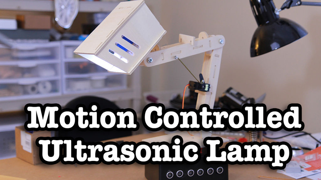
This project demonstrates building a motion-controlled desk lamp using ultrasonic waves to detect movement direction. By integrating three ultrasonic sensors with an Arduino Uno and two high-torque servos, the system responds to swipes left, right, forward, and backward to adjust the lamp's position automatically. The setup involves connecting hardware components on breadboards and programming the Arduino with the NewPing library to interpret sensor data and control servo motors for rotation and vertical adjustment.
Parts used in the Motion Controlled Ultrasonic Lamp:
- Ultrasonic Sensors (x 3)
- Arduino Uno
- High torque servos (x2)
- AA Battery holder
- 6x4x2 Project Box
- Toggle Switch
- Desk Lamp
- Dremel and/or Drill
- Soldering equipment
- Breadboard and wires
Recently I’ve been learning about Ultrasonic waves and how to harness their power. It’s simple enough to make some type of sonar device, but I wanted to take at a step cooler and see if I could use Ultrasonic waves to not only detect movement, but also the direction of that movement. So let’s take it to the ultimate level of awesomeness and use ultrasonic waves to make a motion controlled desk lamp. There’s a lot to do, so let’s get tinkering!
Step 1: What You Will Need
If you want to follow along with this project here’s a list of parts you will probably need to order:
- Ultrasonic Sensors (x 3) = $7.20
- Arduino Uno = $25.00
- High torque servos (x2) = $12.56
- AA Battery holder = $1.91
- 6x4x2 Project Box = $6.49
- Toggle Switch = $3.49
- Desk Lamp = $22.69
Here’s a list of other parts and tools that you you will probably find around the house (as I did):
- Dremel and/or Drill
- Soldering equipment
- Breadboard and wires
Step 2: Connecting the Components
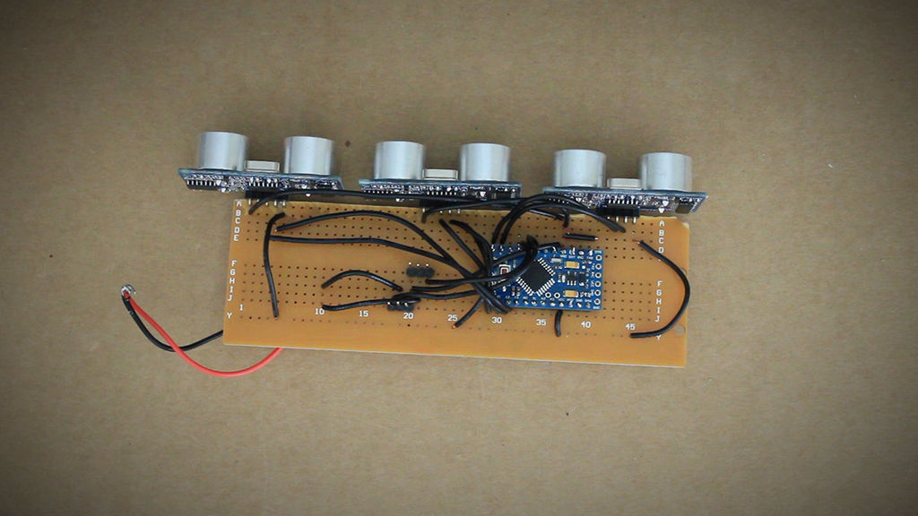
Alright, let’s start connecting the hardware first. We’re going to be using three ultrasonic sensors. They’ll be used to detect swipe left, swipe right, and forward and back movement. Depending on what type of utrasonic sensor you have, you may have a different ammount of pins. Mine has 5, but we’ll only be using four. You want to connect a ground port on the Arduino to the negative row on the breadboard and the 5v port to the positive row on the breadboard.
Now you can now connect the ground pins of the sensors to the ground row, and the VCC pins to the positive row. On the left sensor connect the Trig pin to port 8, and the echo to port 9. For the center sensor, trig goes to 10 and echo goes to 11. And for the right sensor, trig goes to 12 and echo goes to 13.
Using a separate breadboard, let’s connect the servos. Start by connecting both ground wires together and both power wires together. Then connect a power supply to the motors. But you have to make sure you also connect the ground to a ground on the Arduino. Eventually this power supply will power both of the motors as well as the Arduino. Now connect one servo to port 6 on the Arduino and the other one to port 7. Then connect the Arduino up to your computer and let’s start writing code!
Step 3: Writing the Arduino Code
When you have everything connected up the next step is to plug the Arduino into your computer and start writing code for it. You can download the code or copy and paste from below, but before you can run it, you will need to download the NewPing Arduino library and unzip it to your Arduino Libraries folder.
/*BEGIN ARDUINO CODE*/
/*IMPORT NECESSARY LIBRARIES*/<br>#include  //Import the "NewPing" library for the Ultrasonic Sensors
#include  //Import the server library
/*DECLARE ALL VARIABLES*/
int slide = 0; //Slide detector variable
boolean left=false; //Left true/false variable
boolean center=false; //Center true/false variable
boolean right=true; //Right true/false varialbe
#define leftTrig 8 //left sensor output Arduino pin
#define leftEcho 9 //left sensor input Arduino pin
#define centerTrig 10 //center sensor output Arduino pin
#define centerEcho 11 // center sensor input Arduino pin
#define rightTrig 12 //right sensor output Arduino pin
#define rightEcho 13 //right sensor input Arduino pin
Servo servoRotate; //Servo that will rotate the lamp
Servo servoUpDown; //Servo that will move the lamp up/down
int servoRotatePin = 4; //Rotational servo Arduino pin
int servoUpDownPin = 5;//Vertical servo Arduino pin
const int maxD = 20; //cm; maximum distance
For more detail: Motion Controlled Ultrasonic Lamp using Arduino
- What is the primary function of this project?
The project uses ultrasonic waves to detect movement direction and control a desk lamp. - How many ultrasonic sensors are required for the build?
Three ultrasonic sensors are needed to detect swipe left, swipe right, and forward and back movements. - Which pins connect the left sensor to the Arduino?
The Trig pin connects to port 8 and the echo pin connects to port 9. - Can I use a different number of pins on my ultrasonic sensor?
Yes, depending on the sensor type you may have a different amount of pins, but only four are used in this guide. - What library must be downloaded before running the code?
You need to download the NewPing Arduino library and unzip it to your Arduino Libraries folder. - How are the servos powered in this circuit?
A separate power supply is connected to the motors and also grounded to the Arduino. - What is the maximum distance defined in the code?
The constant maxD is set to 20 cm as the maximum distance.