Summary of MOSFET-based Joule Thief steps up voltage
This article describes a MOSF-based Joule Thief circuit designed to step up low input voltages using coupled coils and a photovoltaic optocoupler for isolation. The design employs a low-threshold MOSFET (Q1) and an IR LU3103 MOSFET (Q2) for regulation, utilizing a toroidal ferrite core transformer. It achieves operation at input voltages as low as 0.6V, though regulation is limited by the sharpness of the threshold voltage.
Parts used in the MOSF-based Joule Thief:
- Low-threshold MOSFET Q1
- Coupled coils L1 and L2
- Toroidal ferrite core
- Photovoltaic optocoupler TLP191B
- MOSFET Q2 IRLU3103
- Potentiometer R5
- Capacitor C1
- Resistor divider R1 and R2
The output will be pulses of voltage that can be filtered using a diode and capacitor. As there is no regulation, the output voltage will vary with the input voltage or load. As this circuit uses a BJT, the supply voltage needs to be at least 0.7V to work, and with enhancement-mode MOSFETs, the supply voltage must usually be even higher.
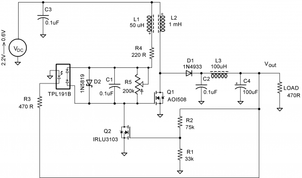
In this Design Idea, a low-threshold MOSFET (Q1) is used with coupled coils L1 and L2 to act as a Joule thief circuit.
A toroidal ferrite core is used to make the coupled coil or transformer. A photovoltaic optocoupler, TLP191B, is used to circumvent the problem with the threshold voltage. Part of the output is used to power TLP191B to make an isolated voltage source in series with the gate of Q1 (AOI508). This isolated voltage can be controlled by the pot R5; capacitor C1 is used to pass the pulses produced by L1 to the gate for switching.
For regulation, another MOSFET, Q2 (IRLU3103), is used. The threshold voltage of Q2 is used to regulate the output voltage. When the output reaches 5V, the divider formed by R1 and R2 makes Q2 conduct, and the oscillation ceases, causing the output voltage to drop. As the threshold voltage is not very sharp, the regulation is not usually that good.
To start working, the circuit initially needs higher voltage than the Vth of Q1. At 1.9V, the circuit oscillates, and the output voltage is 5.1V. As the input voltage goes down, the oscillator stops at 1.4V. By adjusting pot R5 to higher values, the minimum operating voltage can go as low as 0.6V. The input-output voltages are shown graphically in
FOr More Details: MOSFET-based Joule Thief steps up voltage
- How does the circuit achieve low voltage operation?
A photovoltaic optocoupler creates an isolated voltage source in series with the gate of the low-threshold MOSFET. - What component acts as the transformer?
A toroidal ferrite core is used to make the coupled coil or transformer. - How is the output voltage regulated?
A second MOSFET conducts when the output reaches 5V, causing oscillation to cease and the voltage to drop. - What is the minimum operating voltage achievable?
By adjusting the potentiometer, the minimum operating voltage can go as low as 0.6V. - Does the output voltage remain constant?
No, there is no regulation, so the output voltage varies with the input voltage or load. - Why is the regulation not very good?
The threshold voltage of the regulating MOSFET is not very sharp. - What happens if the input voltage drops below 1.4V?
The oscillator stops working when the input voltage goes down to 1.4V without adjustment. - Which specific MOSFET is used for regulation?
The IRLU3103 MOSFET is used to regulate the output voltage.