Summary of MorseCard – A Tiny Telegraph Station
The MorseCard is a DIY weekend project enabling users to create a personal telegraph station. It features a high-contrast OLED screen for deciphering Morse code, educational quizzes, and the ability to communicate between multiple units via speaker wire. The build involves soldering various components onto a custom PCB and programming an ATtiny84 microcontroller with specific sketches to manage input and display output.
Parts used in the MorseCard:
- MorseCard PCBs
- 0805 LEDs
- Diodes
- ATtiny84 microcontroller
- Resistors
- Slide switch
- Buttons
- Terminal block
- JST connector
- Programming headers
- OLED screen
- Lithium polymer battery (implied by Lipo reference)
Story
Behold: the MorseCard! Fulfill your dreams of becoming a telegraph operator (or just make something cool to show your friends) with this weekend project. The MorseCard features a high-contrast OLED screen that will decipher whatever you tap out. I have written a variety of different sketches for the MorseCard, as the video above shows, that can do things like teach you Morse code, allow you to write out sentences without having to worry about the timing of letters or spaces, and communicate with other MorseCards using some speaker wire.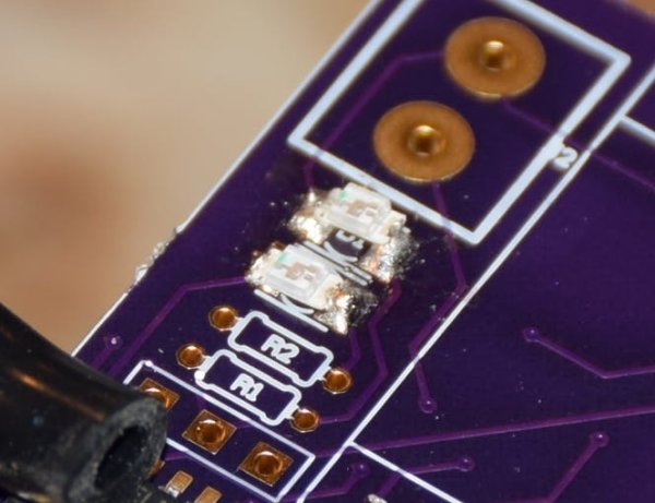
The components list has quantities that are for building two MorseCards. If you don’t want to use the communications features and just want to have one MorseCard to play with then halve all the quantities and don’t buy the speaker wire. Let’s dive in!
Step One: Ordering the Components
You can order some MorseCard PCBs using the link in the components section. They will take about two or three weeks to arrive at your door, giving you plenty of time to source all the other needed components. Depending upon what you have lying around and what you need to order each assembled card should cost around $10-$15.
If you want to customize the PCB to suit your liking you can find the circuits.io link here: https://circuits.io/circuits/5104502-morse-code-walkie-talkie-lipo#pcb
Step Two: Soldering the LEDs
When assembling a printed circuit board I generally like to start with the hardest components and work backwards. The 0805 LEDs are definitely the hardest part of this circuit, so start on these! The diodes I linked to on Amazon have a marking on the back that tells you their polarity. The following image will help you identify your own diode:
Now that you know the polarity, you can solder the LEDs onto the pads! The side of the pads closest to the edge of the PCB is the negative side.
When soldering the LEDs I like to place some solder onto each of the pads, hold an LED in one hand with some tweezers, then use a soldering iron to melt the solder onto the LED, fixing it in place. I then add more solder to the unmelted side. I did a pretty poor job of soldering the above two LEDs in place – this was before I figured out the trick I just described.
Step Three: Soldering the ATtiny
The ATtiny is quite a bit easier to solder than the 0805s. I like to hold it in place with an alligator clip or something like that while I’m soldering the first leg in place. Align the dot in the upper left corner of the ATtiny with the corner of the PCB to ensure the pin configuration is correct.
Step Four: Resistors, Slide Switch, Buttons, and Terminal Block
All these components are simple to solder. The resistors, buttons, and slide switch are non-polarized, so the orientation in which you solder them doesn’t matter. For the terminal block just ensure that the openings where you can insert wires are facing outward.
Step Five: JST and Programming Headers
The JST connector is fairly large, so it shouldn’t give you too much trouble to solder even though it’s a surface-mount component. The programming headers obviously aren’t polarized, but you still need to solder them with the openings facing the bottom of the board so you don’t block the holes for the display.
Step Six: The OLED Screen
The last component to solder is the OLED screen. Make sure that the display you ordered has VCC as the left-most pin. Some of the displays that you can find online have ground as the left-most pin which can mess things up big time. Solder on the display and you’re good to go!
Step Seven: The Sketches
The video I linked at the beginning of this build shows what all the different sketches that I created for the MorseCard can do. One of them is a quiz, another allows you to type out sentences without having to worry about the timing of spaces or letters, and the last one allows you to connect multiple MorseCards together.
Step Seven: Programming!
Programming the ATtiny84 is a piece of cake. If you’ve ever used the ATtiny85 before the procedure is essentially the same, just with different pins. This article explains the general setup process for the programming, except of course the ATtiny84 you are programming is soldered on. To program the SOIC variants of any ATtiny the usual procedure is to break out some of the pins, which I have done.
For more detail: MorseCard – A Tiny Telegraph Station
- How much does one assembled MorseCard cost?
An assembled card should cost around 10 to 15 dollars depending on available parts. - Can I build just one MorseCard instead of two?
Yes, you can halve all component quantities and skip buying the speaker wire if you do not need communication features. - What is the best way to identify diode polarity?
The linked diodes have a marking on the back that indicates their polarity. - Which side of the LED pads is negative?
The side of the pads closest to the edge of the PCB is the negative side. - Does the orientation matter for resistors and buttons?
No, these components are non-polarized so their orientation does not matter. - How should the terminal block be oriented during soldering?
You must ensure the openings where wires insert are facing outward. - Why must the programming headers face the bottom of the board?
This prevents blocking the holes required for the display connection. - What pin configuration must be checked on the OLED screen?
You must ensure VCC is the left-most pin, as some displays have ground there instead. - Can I customize the circuit design?
Yes, you can find the circuits.io link to customize the PCB to your liking. - What functions do the different sketches provide?
Sketches include a quiz mode, sentence typing without timing worries, and multi-unit communication.