In Amateur radio, Morse code is used to send messages using a series of short or long pulses which are heard by the operator as audio beeps. The short beeps are known as dots or dits, and the longer beeps are known as dashes or dahs. To be understood, the duration of the dits and dahs as well as the spacing between dits and dahs (the inter-symbol timing) and the spacing between letters and words must all meet the Morse code timing standards.
In the early days of Morse code, single-lever keys (e.g. the J-38 key) were used which required the operator to manually control all timings. Now most operators (except for the single-lever purist) use a double-lever key known as an iambic key or iambic paddle. I will not discuss the details of iambic paddles here since there are better explanations that can be found elsewhere (search YouTube), but in summary, iambic paddles reduce operator workload by automatically handling the symbol and inter-symbol timing, but the operator still needs to manually control letter and word spacing.
The purpose of this iambic trainer is to help the operator improve sending speed while maintaining proper letter and word spacing.
Supplies
- Arduino Uno (probably would also work with a Nano)
- I2C LCD display (20 char x 4 rows)
- 2 x 3.5mm audio jacks
- 1 x pushbutton switch
- 3D printed case
- 4 x 25mm M3 screws
- 8 x 6mm M3 screws
- Arduino hook-up wire
- right-angle square-pin headers
- heat-shrink tubing
Tools
- a reamer (rotary cutting tool) is handy but not essential
- soldering iron
Step 1: 3D-Print the Case
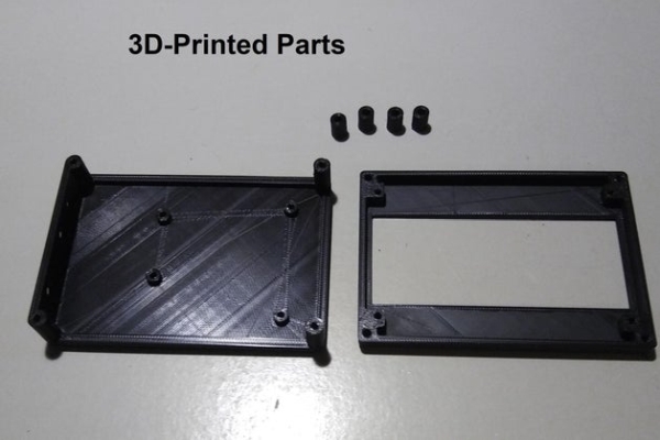
Print the case using the files from Thingiverse https://www.thingiverse.com/thing:4875668
Note: 3D-printed holes are not perfectly round. A reamer is an easy way to clean them up.
Always follow safety rules when using any tool !!
Step 2: Mount the LCD Display in the 3D-printed Bezel
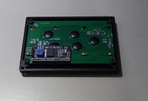
Use four 6mm M3 screws to mount the LCD into the 3D-printed Bezel
Step 3: Add Right Angle Headers to the Uno
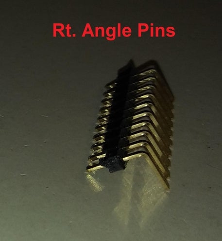
To keep the overall height of the final packaged iambic trainer a bit lower, I installed right angle headers next to the standard Uno headers. Once the headers are installed, the Uno can be mounted in the 3D-printed base using four 6mm M3 screws.
Step 4: Wiring
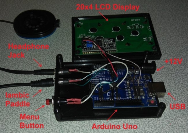
I used Arduino hookup wire with square-pin connectors to wire the project. One end of the wire is clipped and soldered (according to the wiring diagram), I then put a short length of heat shrink tubing over the soldered joint. This helps keep the wire stable and it looks neater. The other end of the Arduino hookup wire is pushed on to the right-angle connectors on the Arduino.
The connections are as follows:
- Arduino Pin2 .. to 3.5mm paddle connector tip (dit)
- Arduino Pin3 .. to 3.5mm paddle connector ring (dah)
- Arduino Pin7 .. to pushbutton switch
- Arduino Pin8 .. to 3.5mm headphone connector tip
- Arduino SCL .. to I2C LCD SCL
- Arduino SDA .. to I2C LCD SCL
- Ground .. wire as per wiring diagram
Step 5: Finish Assembling the Case
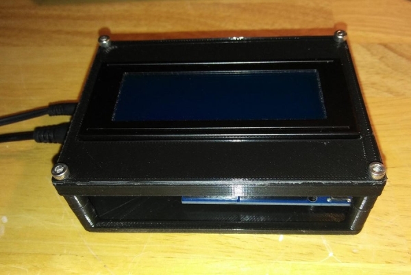
Insert the four 10mm spacers between the base and the bezel and use four 16mm M3 screws to connect the bezel to the base.
Step 6: Programming the Arduino

I will assume that for this project you already have the Arduino IDE installed and that you know how to use it. I will not cover the details of using the Arduino IDE here. If you are unfamiliar with the Arduino IDE, I recommend browsing YouTube for tutorials.
The source for this project can be found here: https://github.com/scottlbaker/morseKeyers/tree/ma…
You will also need the I2C LCD library LiquidCrystal_I2C.h which can be found here: https://www.arduinolibraries.info/libraries/liquid…
Once you have downloaded the source and library, use the Arduino IDE to compile the source and to upload the compiled code to your Uno.
Step 7: Power-On and Test
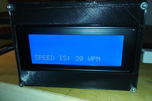
The Arduino can either be powered via the barrel connector (12V) or via the USB connector (5V). I prefer to use the 5V USB connection and either a wall-wart 5V Power supply or a 5V USB battery pack for portability.
A single click of the pushbutton will enter the speed control (words-per-minute) menu. While in this menu the dit paddle decreases the speed and the dit paddle increases the speed. A second click of the menu pushbutton will enter the keyer mode selection menu. The choices are iambic-A and iambic-B. Since I normally use iambic-A, iambic-B is less tested.
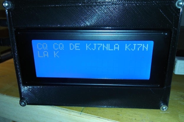
When not in one of the menu modes, the trainer will translate from Morse code and print the resulting ascii character translations.
That’s the end of this instructable. Enjoy your new iambic trainer and let me know if you find any bugs or have any improvements to share.
Source: Morse Code Iambic Trainer and Decoder