Summary of How to Build 8x8x8 LED Cube
This article details the construction of an 8x8x8 LED cube utilizing the Persistence of Vision principle to create mesmerizing 3D light patterns. By controlling 64 LEDs at a time rapidly, the project simulates the illumination of all 512 LEDs simultaneously. The guide covers testing and bending LEDs, constructing eight 8x8 layers using Sunboard and MDF, stacking them vertically, and assembling the circuit with an Arduino Nano and supporting components for a strong, concealed final build.
Parts used in the 8x8x8 LED Cube:
- Arduino Nano
- LEDs (5mm) – 512
- 100Ω Resistors
- 2N2222 NPN Transistors
- 74HC574 Octal D Flip-flop
- 120-pin IC Socket
- 816-pin IC Socket
- Power ON LED
- 15V Power Supply
- Male Headers
- Female Headers
- Connectors with Headers
- Connecting Wires
- Sunboard
- MDF board
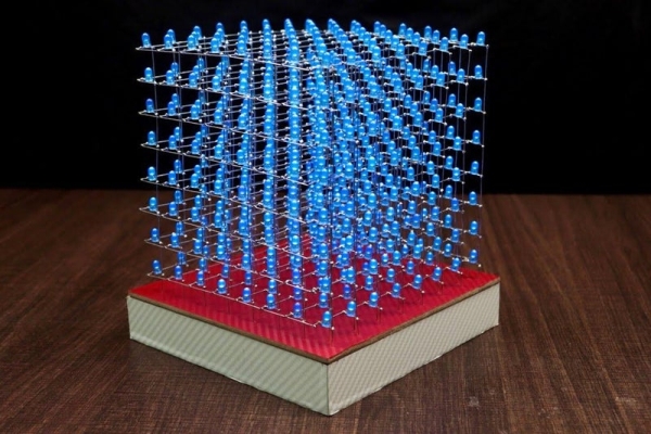
An 8x8x8 LED cube is a visual treat with 3D effects and patterns. It works on the concept of Persistence of Vision, a feature of the human eye which tricks our brain in to thinking that an object is present permanently at a place if it appear about 60 times in a second.
Since an 8x8x8 LED Cube consists of, well 8x8x8 = 512 LEDs, we cannot control all these 512 LEDs at once. What we can do is control 64 LEDs at a time at an extremely fast rate and trick our brain as if we were controlling all the 512 LEDs.
This LED Cube will light up any party.
Your friends will be mesmerized by its hypnotic effect as lights dazzle and dance in brilliant patterns.
This cube gives of a warm glow that is pleasant to the eye and will entertain people of all ages .
Though it might be quite a commitment to build, the effort will be worth the wait.
Surprise your friends and family with this incredible art piece, as it will be sure to turn heads.
Don’t skip this wonderful electronics project because it offers invaluable opportunities for electronic construction and Arduino coding.
visit My website DiY Projects Lab having more than 25 awesome detailed projects
Supplies
Arduino Nano
LEDs (5mm) – 512
100Ω Resistors
2N2222 NPN Transistors –
74HC574 Octal D Flip-flop –
120-pin IC Socket –
816-pin IC Socket –
1Power ON LED –
15V Power Supply
Male Headers
Female Headers
Connectors with Headers
Connecting Wires
Tools
Stripper
Soldering Iron
Solder Helping Hands
Wire
Cutters/Strippers
Needle Nose Pliers
Vice
Step 1: Video
The following video shows how to build 8x8x8 LED Cube.
my website DiY Projects Lab having more than 20+ detailed projects so you can by (click here)
go for a more creative and amazing projects and tutorial.
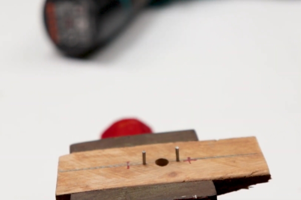
Step 2: Test the LEDs
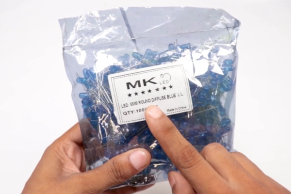
As I’ve already mentioned earlier, we need 512 LEDs.
The first step is to test all the 512 LEDs. You can use a 3V Lithium Cell to test the individual LED.
This step is very important because once you begin soldering the LEDs, it will be difficult to remove them.
They will need to be stable and bright. This step will show you how to separate the faulty ones from the usable ones.
Step 3: Difference Between Diffused and Transparent LED
Step 4: Bend All LED
Start by bending the shorter leg (the cathode) at a 90 degree angle.
Step 5: Building the Layers
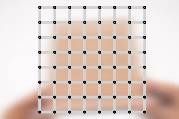
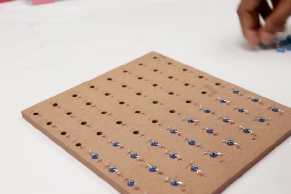
Next step is to create the layers. Each layer is made up of 8×8 LED Matrix consisting of 64 LEDs. In order to build the layers, take a Sunboard and make holes at a distance of 2.5CM. Place the LEDs and start soldering all the cathodes together.
Create an 8x8x8 template so you can create the layers.
You will need a MDF board and you will need to drill holes into the MDF wood board to space the LEDs 1/2″ apart.
Step 6: Layers
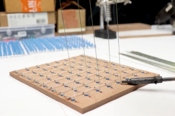
In order to increase the strength of the layer, solder few connecting wires between LEDs.
In addition to acting as support bars, these wires will also short all the cathodes of that particular layer.
Now, test the LEDs once again as replacing a faulty LED will be somewhat easy at this stage.
Once everything is done, put aside the completed layer and continue making seven other layers.
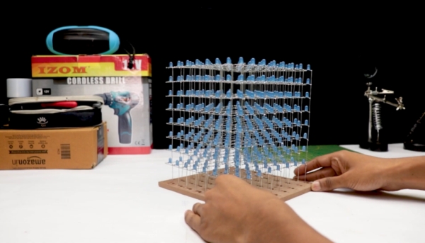
Step 7: Stacking Up Vertical Layers
After completing eight layers, we will now proceed with stacking those layers vertically.
Take a MDF board and mark 64 holes to insert poles for 64 Anode Terminals.
Start soldering layer by layer and use any object like a ruler or even a piece of MDF board to separate the layers.
Step 8:
Step 9: Circuit Diagram
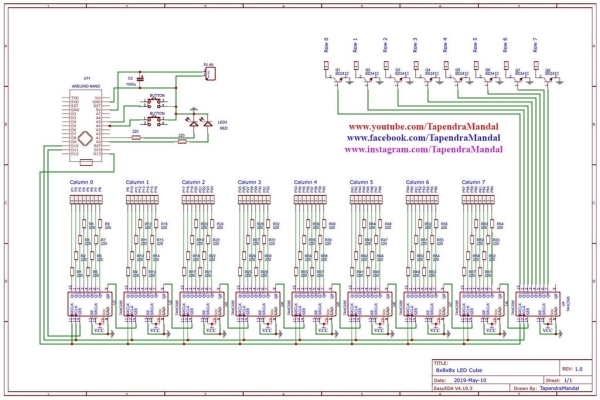
The following image shows the complete circuit diagram of the 8x8x8 LED Cube using Arduino Nano.
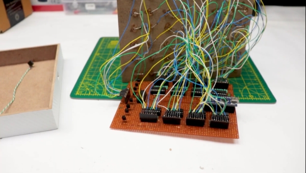
Step 10: Assemble the Circuit
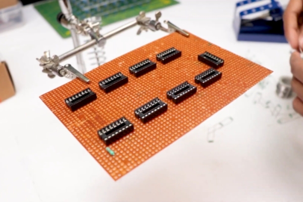
We have designed circuit for this Project:
74HC574 IC’s that get connected to the Anode rows of the LED cube, Arduino Nano, transistors and power supply components.
Thank You NextPCB:
This project is successfully completed because of the help and support from Nextpcb
Guys if you have a PCB project, please visit their website and get exciting discounts and coupons.
Only 0$ for 5-10pcs PCB Prototypes https://www.nextpcb.com…
Step 11:
Step 12: Final Build and Programming
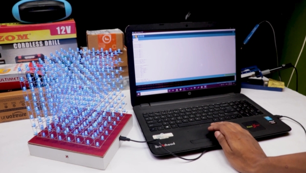
The final build of the 8x8x8 LED Cube is shown in the image above.
The structure is very strong and all the electronics including the power supply are concealed inside the base
The code is developed based on the work of “chr” from Instructables.
There are many codes available in the internet that you can use.
Source: How to Build 8x8x8 LED Cube
- How many LEDs are required for this project?
You need exactly 512 LEDs because the cube consists of 8x8x8 units. - Can I control all 512 LEDs at once?
No, you cannot control all 512 LEDs at once; instead, you control 64 LEDs at a time at a fast rate. - What is the concept behind the visual effects?
The cube works on the concept of Persistence of Vision, which tricks the brain into seeing an object as permanent if it appears about 60 times in a second. - How should I test the LEDs before soldering?
You can use a 3V Lithium Cell to test individual LEDs to separate faulty ones from usable ones before soldering begins. - What material is used to make the layers?
Each layer is made up of an 8x8 LED Matrix built on Sunboard with holes spaced at 2.5CM. - What component connects to the Anode rows of the LED cube?
The 74HC574 ICs get connected to the Anode rows of the LED cube. - What tool is suggested to bend the LED legs?
The instructions suggest bending the shorter leg (the cathode) at a 90 degree angle. - Where can I find more detailed electronics projects?
You can visit the website DiY Projects Lab which has more than 25 awesome detailed projects.