Summary of Momentary Switch as Digital Sensor
This article explains how to use momentary switches as digital sensors with an Arduino. It details the necessity of pull-up or pull-down resistors to prevent floating input pins and describes three wiring methods: external pulldown, external pullup, and using the Atmega chip's internal pullup resistor. The guide includes code examples for each configuration to control an LED based on button state.
Parts used in the Momentary Switch Digital Sensor Project:
- Momentary switch (pushbutton)
- Arduino microcontroller
- Atmega chip
- LED (Light Emitting Diode)
- 10K resistor
- Breadboard
- Connecting wires
In many cases switches are just switches. They directly control the flow of electricity to an appliance, flashlight or mains-voltage lamp. An example of this is the switch on the wall in your living room. In many cases nowadays however, switches are digital sensors, meaning that instead of directly controlling a high-powered device, they are controlling a logic (low power) signal to a microcontroller (eg Arduino), telling the microcontroller which state a user prefers, High or LOW, On or Off, 1 or 0 (they all amount to the same thing).
We don’t often think about switches as sensors, chiefly because they are older technology, with which we are completely familiar. Nevertheless, a switch can always be used as a digital sensor, transmitting one bit of information, which is whether the switch state is Off or On (which can also be defined as 0 & 1).
This wiki entry focuses on momentary switches but it is important to note that many other types of switches, such as toggle switches or slide switches, can be wired in exactly the same manner and used as digital sensors, with the same code examples as used below.
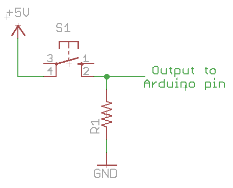
The schematic symbols for switches can vary somewhat. The symbol for S2 is more descriptive of a breadboard-mounted momentary switch but the basic idea is exactly the same, a connection is being created by pushing the switch.
The are a couple of confusing things to consider in using momentary switches. One aspect is that the switch has four leads but only two wires are actually being switched (if you check the schematic symbol). The switching action happens between the leads spaced at the shortest distance. The other two leads are connected internally along the “longer” side of the switch. The middle diagram above shows the idea. You can easily prove out which leads are shorted, if you forget, but using your mulitmeter on the continuity setting (aka “beep setting”).

Why do I need a pulldown or pullup resistor?
Students often have a hard time grasping why we need a pulldown or pullup resistor on a switch. One way of explaining this is in describing the nature of the Arduino pin when it is set to INPUT. The pin is described as being in a “high-impedance state”. This means that it requires very little current to switch the pin from HIGH to LOW or vice versa. Without a pullup or pulldown, the input pin can be thought of as “flapping in the wind” and any small amount of charge is capable of flipping the pin’s state. This charge could come from any capacitive field (all conductors act as capacitors to some extent). Often an Input pin which is left “floating” will capacitively couple to nearby pins and follow them.
The purpose of a pullup or pulldown is to steer a pin into a known state, until the switch is actuated, or an input in sensed. The pullup or pulldown resistor, banishes this “flapping in the wind” and gives the input a known behavior.
Different ways of wiring a switch
There are three different ways of wiring a switch (on an Arduino pin) with a pullup or pulldown resistor.
- A switch may be wired with an external pulldown resistor
- A switch may be wired with an external pullup resistor
- A switch may use the internal pullup resistors in the Atmega chip
/*
  Button Test Sketch (LED optional)
 Turns on and off a light emitting diode(LED) connected to digital
 pin 13, when pressing a pushbutton attached to pin 2.
 The circuit:
 * LED attached from pin 13 to ground
 * momentary switch attached to pin 2 from +5V
 * 10K resistor attached as pull-down resistor
*/
//constants
const int buttonPin = 2;     // the pushbutton pin
const int ledPin =  13;      // the LED pin

// variables
int buttonState = 0;         // variable for reading the pushbutton status

void setup()
{
  pinMode(ledPin, OUTPUT);    // initialize the LED pin as an output:
  pinMode(buttonPin, INPUT);  // initialize buttonPin as an input
                              // not really required (pins default to INPUT)
  Serial.begin(9600);         // initialize Serial for debugging feedback
}

void loop()
{
  buttonState = digitalRead(buttonPin);     // read the state of buttonPin
  Serial.println(buttonState);

  if (buttonState == HIGH)       // check if the pushbutton is pressed.
  {
    digitalWrite(ledPin, HIGH);  // turn LED on: (send +5V to pin)
    Serial.println("Button is       ON ");    //  print to serial monitor
  }
  else
  {
    digitalWrite(ledPin, LOW);       // turn LED off: (send 0V to pin)
    Serial.println("Button is OFF"); // print text to serial monitor
  }
  delay(200);  // delay so that print to serial monitor is not too fast
}
Momentary switch wired with external pullup resistor
I don’t have photographs of this setup at this time but you might be able to guess from the schematic that you can just switch the wires at the power rails, to their inverse GND becomes +5V and 5V becomes GND. Everything else stays the same.
/*
 Button Test Sketch with external pullup resistor (LED optional)
 Turns on and off a light emitting diode(LED) connected to digital
 pin 13, when pressing a pushbutton attached to pin 2.
 The circuit:
 * LED attached from pin 13 to ground
 * momentary switch attached to Arduino pin 2
 * other side of momentary switch attached to GND
 * 10K resistor attached as pullup resistor to 5V
*/

//constants
const int buttonPin = 2;     // the pushbutton pin
const int ledPin =  13;      // the LED pin

// variables
int buttonState = 0;         // variable for reading the pushbutton status

void setup()
{
  pinMode(ledPin, OUTPUT);    // initialize the LED pin as an output:
  pinMode(buttonPin, INPUT);  // initialize buttonPin as an input
                              // not really required (pins default to INPUT)
  Serial.begin(9600);         // initialize Serial for debugging feedback
}

void loop()
{
  buttonState = digitalRead(buttonPin);     // read the state of buttonPin
  Serial.println(buttonState);

  if (buttonState == LOW)        // buttonState is LOW when pressed.
  {
    digitalWrite(ledPin, HIGH);  // turn LED on: (send +5V to pin)
    Serial.println("Button is       ON ");    //  print to serial monitor
  }
  else
  {
    digitalWrite(ledPin, LOW);       // turn LED off: (send 0V to pin)
    Serial.println("Button is OFF"); // print text to serial monitor
  }
  delay(200);  // delay so that print to serial monitor is not too fast
}
Momentary switch wired with internal pullup resistor
Once you have the sketch above working, you can just eliminate the pullup resistor. We will use the Atmega (Arduino) chip’s internal pullup resistor. This simplifies the switch wiring a bit. The only down side to this arrangement is that it might be slightly harder for beginners to think about LOW as being the active (pushed) state than “HIGH”.
For more detail: Momentary Switch as Digital Sensor
- Why do I need a pulldown or pullup resistor?
A pullup or pulldown resistor steers the pin into a known state to prevent it from flapping in the wind due to high-impedance input characteristics. - How many leads does a momentary switch have?
A momentary switch has four leads, but only two are actually being switched while the other two are connected internally. - Which leads on a switch are shorted during the switching action?
The switching action happens between the leads spaced at the shortest distance. - Can toggle or slide switches be used as digital sensors?
Yes, toggle switches or slide switches can be wired in exactly the same manner as momentary switches to function as digital sensors. - What is the benefit of using the internal pullup resistor in the Atmega chip?
Using the internal pullup resistor simplifies the switch wiring by eliminating the need for an external component. - What happens if an input pin is left floating without a resistor?
A floating input pin can capacitively couple to nearby pins and follow them, causing unpredictable state changes. - How does the code logic change when using an external pullup resistor versus a pulldown resistor?
With an external pullup resistor, the buttonState is LOW when pressed, whereas with a pulldown resistor, it is HIGH when pressed. - What setting should be used on a multimeter to verify which switch leads are shorted?
You should use the continuity setting, also known as the beep setting, on your multimeter.