Hello everyone!
My age is twenty years. I started using my Arduino for the first time during Christmas, and I have been busy working on Arduino projects to create this instructable for you. I trust that it will be beneficial!
The purpose of this project was to build a stepping stone from remote controlled flight to completely autonomous flight. This initially seemed like a daunting process, but by breaking it up it becomes manageable. I think that if you have completed any kind of autonomous robot, and you have access to an RC airplane, you are in good position to take on autonomous flight. If you haven’t done so already I would HIGHLY recommend visiting the site http://diydrones.com. There are TONS of relevant threads with many helpful members. Plus, plenty of inspiration. If you’d like, please look me up; my username is waymond91.
You have the option to purchase a full platform for creating your own independent flyer and also access a full code for download!!!
Nevertheless, like most instructables users, financial constraints often restrict the ability to purchase ready-made items, leading to immense gratification in crafting something from scratch.
I had two primary objectives when beginning this project:
1) Achieve sustained level flight using our autopilot program
2) Ability to switch between radio controlled and arduino controlled flight
I suggest that you should already possess some knowledge of flying RC airplanes; otherwise, you should find your own plane and practice flying it. I’m not going to explain how to build an airplane; my main focus is on the autopilot system. Perhaps consider modifying a plane that you already own.
Having prior knowledge of will put you in a strong position.
I enjoy using my Ubuntu terminal to discover and download new Arduino libraries within the Arduino programming environment.
The arduino servo library is the same as before.
The library for arduino wiring (used for I2C communication – when necessary)
Fundamental grasp of arrays and pointers
If these concepts are unfamiliar to you, I trust that my guide will be beneficial. You should be able to solve it regardless. There are many additional websites containing excellent information!! You might want to give a PING robot or a line follower a try. 🙂
Keep moving forward no matter what!
We will be acquiring knowledge about:
The process of data cleaning and analysis with PID loops and cascading PID loops.
Unfortunately, I couldn’t make the embedding feature work, so all the videos in this instructable are accessible through hyperlinks.
This is one of my initial tests, and as you can observe, we still need to address some jittering issues.
http://www.youtube.com/watch?v=Im0Sm7hgn-8
Step 1: Sensors
Two sensors are being utilized for airplane control: an accelerometer for the plane’s angular position, and a gyroscope for the plane’s angular velocity.
These sensors are typical when attempting to build your own IMU (inertial measurement unit). I employed sensors from the ossep brand that are built on the ADXL345 accelerometer, and MPU 3050 gyroscope.
http://osepp.com/learning-centre/start-here/gyroscope-sensor-module/ & http://osepp.com/learning-centre/start-here/accelerometer-sensor-module/
The Pros of using these sensors:
Available at Frys
Code available online
I2C protocol makes wiring easy
Cons:
Headers are bigger than the actual circuit
Electric motor easily induces noise on the sensor/wires (may not be due to this specific brand)
Converting outputs to proper units took me a while
I will go over how to clean up sensor values a little later.
I do not think you should have to use I2C protocol to get this plane off the ground, it is just what was available to me at the time. There are lots of other good IMU units available online. Check Sparkfun!!
http://www.instructables.com/id/Accelerometer-Gyro-Tutorial
http://www.robotshop.com/
don’t forget adafruit
While I am adding links… I have only tried the diavolino with some success but these small arduino compatibles look like they’d fit in a model plane nicely.
http://rasterweb.net/raster/2010/11/05/cheap-arduinos/
Step 2: Control Method: Proportional Integral Derivative Control
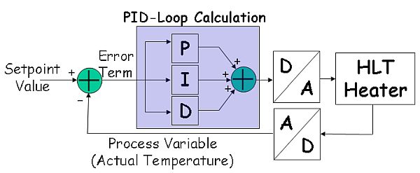
While the autopilot is active, it will detect both the plane’s angular attitude and the desired attitude. The error is what separates the expected from the real. Next, we will adjust the angles of our servo output in order to modify the angles of our control surfaces (ailerons and elevator) and correct the mistake. The issue arises: how can we connect our sensor data to our servo controls?
The answer: A PID controller.
A PID controller utilizes three terms to compute a result that is expected to rectify the mistake.
Result equals the sum of the product of proportional gain and error, integral gain and error sum, and derivative gain and derivative of error.
The initial term, known as the proportional term, evaluates our present inputs (pitch and roll in this scenario) and contrasts them with the desired position, also known as the setpoint (0 degrees to maintain level flight). The error calculation is scaled by a constant (KP) to limit it within the output boundaries (servo range is 0 to 180 deg, but is usually narrower in an RC aircraft). Essentially, the more mistakes there are, the more significant the adjustments needed.
The term following the first is the integral term. It adds up all past mistakes (measured by the proportional component) throughout time. If the error is not fixed soon, the integral term will continue to increase, causing our output to grow until the error is addressed. Once more, use your constant (KI) to scale the term within the output limit *CAUTION* Continuous accumulation of errors may result in the integral term surpassing your output capacity. This phenomenon is known as INTEGRAL WINDUP. It took me a while to repair this. I reduced the term by narrowing the time frame in which I analyzed my mistake. To avoid overcorrecting based on the first two terms, we need to consider the third term.
The derivative term (dError) evaluates how quickly your sensor inputs are getting closer to your setpoint in order to predict when the error will be fixed. The derivative term helps in reducing the output speed if it is correcting too quickly and is at risk of exceeding the setpoint. Multiply by the constant KD in order to maintain the output within the feasible range.
The PID controller is effective as it relies on prior outputs and inputs for determining the latest output. Reading some material from external sources will prove to be very advantageous if you are unfamiliar with them.
tool. http://en.wikipedia.org/wiki/PID_controller#Control_loop_basics
Once you understand how it works, please look at the structure section on the feedforward control loop.
Step 3: Demo PID Controller
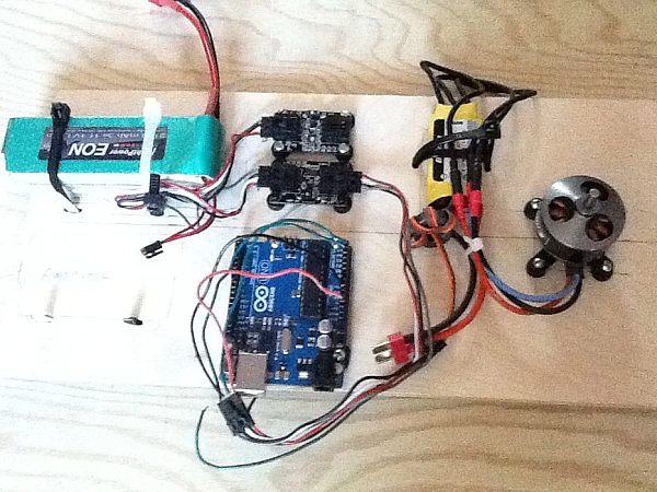
Eflite Outrunner Motor
35 Amp ESC
11.1 V LiPo battery
1/2″ PVC
An aged sawhorse used as a support.
The controller analyzes the arm’s angle with the accelerometer and gyroscope, and then calculates the necessary current to adjust the motor and maintain arm level.
Since the ESC is made for connecting motors to a radio receiver bus meant for servos, it simplifies the process of controlling a brushless AC motor with an ESC on an Arduino using the Servo.h + Servo.cpp files in your libraries directory. I think the servo protocol utilizes pulse position modulation (PPM), which can be done by utilizing a PWM pin on your Arduino using the servo.write() function.
http://www.hooked-on-rc-airplanes.com/servo-tutorial.html
It is important to be saftey conscious when running these motors, as they go extremely fast. *ALWAYS wear saftey glasses* *Leave the propeller OFF until you absolutely need it*
You will have to write a function to arm(); your ESC so that you can set its speed. Basically you need to write the ESC low, high, and then low again.
http://www.arduino.cc/cgi-bin/yabb2/YaBB.pl?num=1226292633 This forum goes over how to control a brushless motor, and is where I got framework for my arm(); function and setSpeed (); function.
You could just use a servo.write(0-180) to set your speed on your esc, but you can also map it on a scale of 0-100. You can download the motor_functions at the bottom of the step. If it doesn’t work please tell me!! I can simply add it into the instructions!!
Using these functions gives you full motor control. You will have to fidget with your own code for your particular ESC. By declaring our sensor functions independently from the loop we can now run the motor and sensors at the same time. This is where I hit my first major setback. Because the motor draws so much current from the battery, it was inducing currents in my I2C bus. My sensor would work fine when the motor was off, but when the motor was running the values were pretty much meaningless.
I took the following steps to clean up the noise:
I added a ferrite ring to the esc (retrospectively, this probably just protects the ESC from noise- learned to use these after my Zagi crashed http://www.hobbyking.com/hobbyking/store/__23206__Clip_On_Soft_Ferrite_Rings_5pc_.html)
I mounted the sensors as far away as possible from the motor
Twisted all my wires to try and minimize current induction
I found these websites to help deal with my problem:
http://diydrones.com/forum/topics/pid-controller-i2c-bus-noise-from-esc?xg_source=activity //this is a thread I started on DIY drones
http://forum.allaboutcircuits.com/showthread.php?t=41916
This seemed minimize sensor error, but still about 5 out of every 20 values were off by +-10 degrees. To clean this up I mediated the sensor values by:
Building an aray to hold 20 values as they appeared chronologically
Building an array that held the last 20 values sorted in (ascending or descending order; it doesn’t matter because we are looking for the median)
I used a bubble sort to help sort my values
I found this website to help explain how to sort array efficiently:
http://mathbits.com/mathbits/compsci/arrays/sorting.htm
You will have to construct multiples of these sorting functions for multiple values (x, y, z; dx, dy, dz)
Download my bubble sort and median functions below!
With your sensors matching and your AC motor under control, we can now start implementing PID control for real!
The Wikipedia page effectively details how your program should be organized through the use of pseudocode. There are numerous ways to carry out this task. The length of time you plan to use your feedback will determine the value of your integral and derivative terms.
My PID_sample can be located at the conclusion of this step!
Adjusting the PID parameters: There are numerous methods for tuning a PID. You have the option to purchase software or use trial and error, but I recommend using the Zieger Nichols method.
In any case, begin by running your output with the proportional error only. Adjust KP to ensure that the proportional term does not exceed the output capacity. In essence, the system will fluctuate, you aim for it to decrease near your desired level (or at least not rise gradually!). After finding a suitable KP, you can choose to adjust either KD or KI. Various opinions exist on the order of actions to take, but using the integral term speeds up correction towards the setpoint and the derivative term slows down overcorrection.
After playing with the code for a while it should become apparent how adaptive this type of controller is to your particular system. Remember, try and feedforward as much as you know how to! Once you are comfortable go ahead and install the controller!!
Step 4: Setting Up the Plane
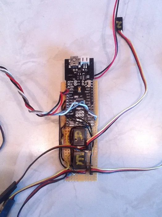
To start testing, I opted for a glider to eliminate any chance of motor disruption. After reaching level flight, I have a Zagi prepared and a multiplex Twin Star for potential drones.
I installed the system on my Swift AT (Aileron Trainer). I am very fond of this glider. Doesn’t need a lot of wind to soar and can perform various maneuvers. Glider flying is wonderful when there is wind, as you can stay in the air for hours without needing to land and refuel, due to the absence of a motor or engine.
Our upcoming board configuration will closely resemble our original PID system; we will execute two PID loops rapidly to manage pitch and roll using the elevator and ailerons. This will provide enough time for testing in favorable wind conditions.
I am utilizing Airtronics radio gear with a transmitter/receiver that has 6 channels. I utilized the radio’s fifth channel, specifically a landing gear toggle, to control the autopilot’s on/off function from the transmitter. Link the servo wire from the receiver to a digital input in order to gauge the pulse length of both positions (on/off). Utilize the pulseIn() function for that purpose. After choosing a value from each of the two states, select one to represent off and the other to represent on. When the arduino detects an ON signal, it must transmit a digital HIGH to activate a relay or trigger transistors. I opted for relays instead of transistors to prevent my signal from passing through a transistor (a choice I would come to regret).
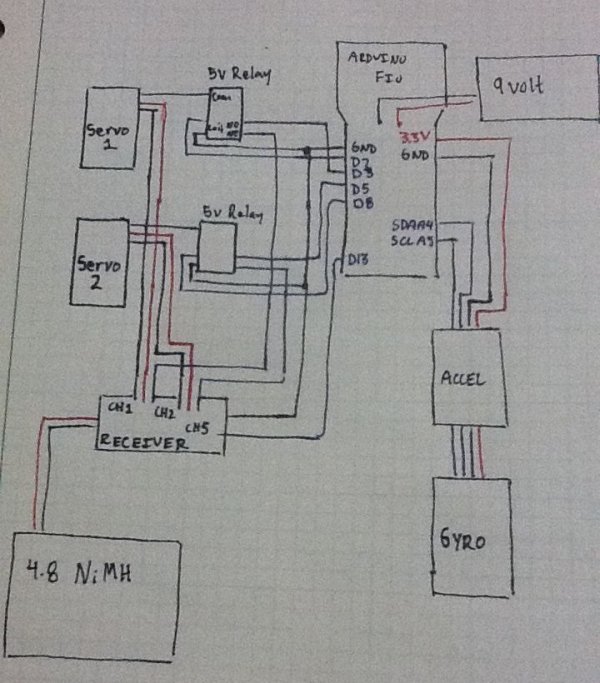
You are able to view the diagrams I sketched for connecting a circuit that would switch a servo from the radio to the arduino. There are two items: one is for transistors and the other is for a radio. Observe the placement of PNP and NPN transistors. If the Arduino output wire is at a low level, the servo signal will be directed to the radio; if it is set to high, it will switch to the board. Similarly, the radio is connected to the normally closed terminal, while the Arduino is connected to the normally open terminal on the relay circuit.
My functions for activating the autopilot can be located at the end of this section.
This video demonstrates the arduino receiving radio signals to activate an LED, which is then used to arm the autopilot system.
Step 5: Here Is My Code and My Schematic!
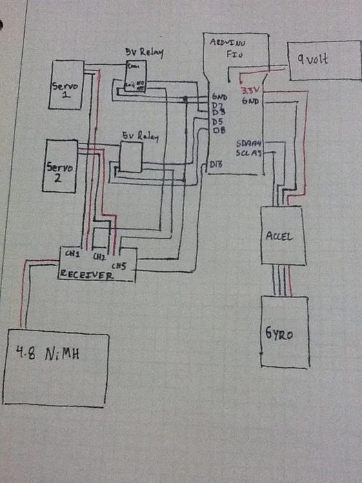
The code begins by guiding us using solely proportional error. After experimenting, you need to determine your own KP KI KD values.
Ensure that the weight distribution of your aircraft is even prior to departure! Activate the autopilot system prior to launching your aircraft and ensure that the throws are aligned in the proper direction.
The code’s fallback function, located at the end, is important for returning control to the receiver in case of sensor errors or potential loops where control is needed from the autopilot. Be sure to include this function in your code.
Get the code provided for download.
Step 6: Success & Failure
Plane self corrects when running autopilot *more trials pending favorable winds*
Switching capability between radio and arduino
Use of PID control can easily be tuned to stabalize a systemFailures:
Arduino Fio did not really have enough juice to run the sensors and switch my 5v relays (FIo operates on 3.3v)
Possible remedies = different arduino (perhaps the nano?) or use transistors **RESULTS PENDING**
Gyroscope data not yet in use
Possible remedies = stop typing up the project and go figure it out 😛
Step 7: Future Development

My upcoming escapade will include the following step:
managing a powered aircraft (we have proven our ability to manage each system)
Using a GPS to track the aircraft’s location and height (fingers crossed for winning this competition!!!)
Creating cascading PID controllers: one PID controller is used to determine the required angle to reach a specific waypoint based on its GPS location, while another PID controller is utilized to adjust the aircraft’s attitude accordingly in order for it to effectively navigate to those waypoints.
Thank you for taking the time to review my guidelines! If you have any input, inquiries, or remarks, feel free to share with me! If you’d like to keep seeing the shift from RC flight to autonomous flight, please upvote and give feedback. I am working towards competing in the robotics competition, and hopefully, we will win a new GPS as a prize. I am taking all necessary steps to make this transition smooth and clear so it doesn’t feel too daunting to undertake alone.
Source: Model Airplane Autopilot using Arduino

