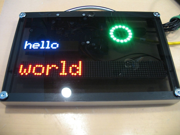
Digital signage can be useful at events to inform visitors about upcoming panels, changes in the schedule or dynamically provide information. Using LED Matrix displays for that makes the messages readable even from far away and is an eye catching feature.
Features include:
- 2 Lines of dot matrix modules, 1 RGB Ring indicator
- http web interface for simple fallback management
- REST/JSON API for advanced remote management
- automatic brightness control
- IR remote control
- I²C interface connector for external modules (e.g. DS1307 RTC)
- wide range power input: 10-20VAC/10-30VDC
- message board and event schedule modules for network independent manual operation
The following instructions will go over the process of building one of these displays with both the electronics and supporting frame in mind. The build process requires some specialized tools and advanced soldering skills. Therefore I’d describe the difficulty level as medium-hard and not suited for beginners.
The full documentation on the software and hardware can be found at gitlab/mirolo-2M05081R16
Step 1: What You Need
You will need a variety of tools to complete this project. This is the basic set. Any tools like CNC machines or belt sanders and drill stands will make your life a lot easier.
- Soldering Station including tips capable of soldering SMD components
- De soldering equipment
- Power Drill
- Hot Glue Gun
- Reciprocating Saw and metal saw blades
- Pliers
- Screwdrivers
- Wrenches and Sockets
- Multi Meter
- Tap and Die
- Countersink Drills
- Drillset
- Vice
- Handsaw
- Two Component Glue
- Sandpaper
- Metal File
- Double Sided Tape
Of course you also need building material. You can find a full list of all the parts needed here: Material List
Important: When buying components like Electrolytic Capacitors make sure their height does not exceed 12mm. Otherwise they will be higher than the matrix display and the board won’t fit properly.
Step 2: Preparing Parts
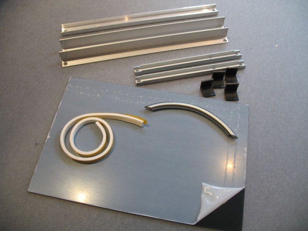
First you need to make the required parts for the frame holding everything together. If you want to design your own frame you may skip these steps entirely. I will keep it very short and only link to the files describing the part’s dimensions. Actually making them involves drilling sawing and patience but you should know how to handle a power drill, saw and file to do this.
Step 3: Electronics Assembly
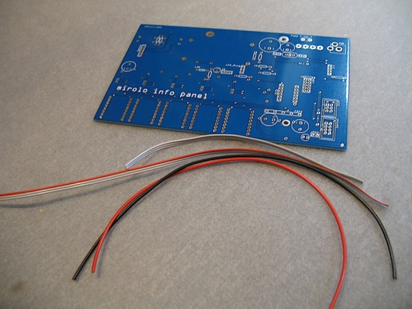
Let’s start with the blinky stuff. Have all the parts shown above ready. The full Material list is linked in step 1.
Concerning the PCB I highly recommend having them made by a professional company. Some traces are quite thin and it took me several tries to even get a working prototype that wasn’t completely botched and I still had electrical problems because of etching errors that were a nightmare to work out. The design works great but the board is a bit too complex for home etching. Unless you have semi professional etching equipment at hand it’s really not worth the effort. Especially considering that you need to bend 48 jumper wires for each of these when using the singlesided design. This is the stuff that will give you nightmares. I got my own from JLC-PC and their quality is really nice. They saved me hours of work and lots of material.
I still have 5 of these lying around. If you are interested in making this project yourself send me a note and we’ll work something out. Might be easier to ship them from Germany instead of ordering new ones from China.
Step 4: Electronics Assembly – 8 Module Matrix
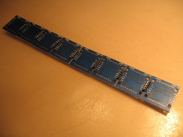
We’ll start off with the lower matrix bar. This one consists of 8 FC-16 modules. Solder them together to form a single line. You can use the included 90° pin connectors by bending them into a 180° shape using pliers. I recommend gripping them in a vice.
Connect all the modules and solder one of the 3 pole ribbon cables to the data input as well as the two stranded wires to the power input.
When soldering the matrix modules on top please DO NOT USE the provided female pin connectors. Otherwise the module will be too thick to fit in the frame. Keep the connectors though as you will need them for the other display line. Also make sure they are oriented correctly.
Solder the 1000µF Capacitor at the end (Data OUT) of the strip to GND and VCC as an additional buffer.
Step 5: Electronics Assembly – WS2812 Ring
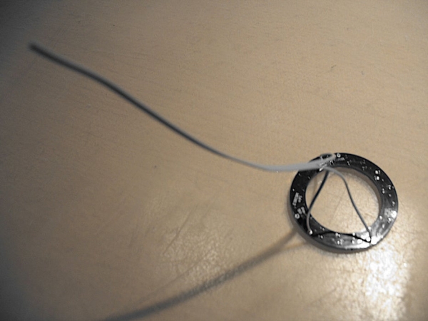
Solder the other 3 pole ribbon cable to the ring (middle pin of the cable should be GND)
Source: Mirolo Networked LED Matrix Display for Digital Signage