Summary of Mini High Voltage Supply Using Arduino
This project describes a high voltage power supply generating 10 to 20 kV DC pulses using a 555 timer-based oscillator driving a transformer and a Cockroft-Walton voltage multiplier. It is suitable for educational experiments such as electrostatics or ignition testing, but involves dangerous high voltage and must be handled with caution. Voltage output depends on the number of multiplier stages, and safety considerations include proper capacitor discharge and avoiding interference with sensitive electronics. The design uses an IR LED and sensor for switching, with adjustable frequency and duty cycle.
Parts used in the High Voltage Supply:
- 555 timer IC
- 8-pin chip socket
- Transformer body with enameled copper wire (or 8R:1kOhm audio transformer)
- 220µF capacitor
- 2 × 1kΩ resistors
- 10 × UF4007 diodes
- 10 × 10nF 1kV to 3kV ceramic capacitors (recommended 2kV)
- 2n2222 transistor
- BD679 (or equivalent Darlington high current, fast-switching transistor)
- Small heatsink
- 10kΩ or 4.7kΩ potentiometer
- IR LED
- IR light sensor
- 30Ω resistor
- 2 × AA battery pack
- Shrink tube (5mm diameter)
- Two push buttons
WARNING: Before you start making anything please take a moment and read this:
- This circuit is intended to be used for educational and experimental purposes (electrostatic experiences, franklin bell experiment, plasma generation, gas ionization, electronic igniter, testing of insulating materials…) this circuit should not leave the lab or your house, and it shouldn’t be used to harm to anybody, human or animal.
- Do not attempt to replicate this circuit if you aren’t familiar with high voltages or intermediate electronics, high voltages are very dangerous. This voltage supply uses small capacitors to achieve a desired voltage, remember to safely discharge those capacitors by shorting the output when you finish using the supply to avoid accidental shocks (it hurts, but the energy stored in the 10nF caps is very small to be dangerous). Take into account the sparks and corona discharges generate ozone, so use it in well ventilated areas.
- High voltages can disrupt electronic equipment, so don’t keep phones, pacemakers or other sensitive electronic devices near the supply.
- I’m not responsible for the use given to this device and I’ve made all what it’s on my hands to include safety related information, and safety implementations to the circuit.
Follow the general security measures when dealing with high voltages, here you have a nice safety guide, please read it carefully before you continue.
Although this device outputs a huge voltage, the associated current is extremely small, but it can still be dangerous and produce a quite nasty and painful shock.
In terms of safety, this is one of the safest high voltage sources, since the current output is comparable to the tasers used by the police. It’s a safer alternative to more dangerous power supplies made out of TV flyback transformers. Nevertheless the dangers can’t be underestimated.
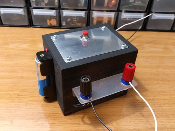
Step 1: Introduction
This high voltage supply is designed to output alternating pulses of DC voltage around 10 to 20 kilovolts, I haven’t really measured the voltage, but the spark gap can get as long as 1.5 Cm, this can vary due the different elements used to make the circuit.
The voltage itself can be regulated varying the amount of stages at the Cockroft-Walton multiplier, for example, if you want it to lit a neon bulb you can use 1 or no stages at all, if you want to power a sparkplug you can use two or three, and if you want a higher voltage you can use 4, 5 or more.
Bear in mind less stages mean less voltage, but more current, what could increase the dangerousness of this device. Ironically, the more voltage you get, the less difficult is to be harmed by the supply, since the current drops to a negligible point.
Also, take into account the Cockroft-Walton multiplier isn’t ideal, so the more stages you add, the more losses you’ll get, until you reach a point where more stages mean a decrease in the voltage, I recommend 5 stages, although I haven’t tried to use more.
At the top you have a short video in which I test it:
Step 2: How it works:
Understanding how this circuit works is not crucial to be able to assemble it and make it work, you can skip this part if you want, but it’s nice to know how things work:
After pressing the button, the IR diode is activated and a beam of light hits the sensor of the optocupler, this sensor drops it’s resistance to about 50 Ohms, unleashing the energy needed to activate the 2n2222 transistor.
This transistor allows some energy to power the 555 timer. For those of you who don’t know what a 555 timer is, it is a chip, that, amongst other functions, can take an input DC voltage and transform it into a square wave. The frequency and duty cycle of the wave can be adjusted modify the value of the components that surround it.
In this case it’s adjusted to have a constant 50% duty cycle, while the frequency can be adjusted with the potentiometer.
This square wave, gets sent to a high current transistor, which allows pulses of high current to flow inside the primary coil, and here is where the magic happens. I also added a small 220uF capacitor, it’s function is to save some energy while the transistor is off, so it can release current quite fast when it turns on again, this will release some stress from the power supply since the variations of current won’t be that high between pulses.
You can charge up a coil with a magnetic field the same way you charge a capacitor with static charges, the difference is when the magnetic field is no longer sustained, it collapses, converting that energy into a voltage spike.
The amplitude of that spike depends on the turn ratio, and since it’s quite large we can get big voltage spikes at the output of the transformer. But that voltage is still far away from the voltage we’re looking for, so that’s why we add a Cockroft-Walton voltage multiplier, which steps up the voltage until its high enough to break air resistance.
You can learn more about voltage multipliers here.
Step 3: The big list
You will need:
- 555 timer
- 8pin chip socket
- A transformer body and enameled copper wires (winding our own transformer will give us a bit more of power than the 8R:1kOhm audio transformer, also it’s kinda difficult to find that specific audio transformer)
- 220uF capacitor
- 2x 1k resistor
- 10x UF4007 diodes ( they are faster than the 1N4007, meaning better performance)
- 10x 10nF 1, 2 or 3KV ceramic capacitors. I recommend 2kV ones.
- 2n2222 transistor
- BD679 or similar high current – fast switching Darlington transistor
- Small heatsink
- 10kOhm or 4.7kOhm potentiometer (for more accuracy)
- IR LED
- IR light sensor
- 30 Ohm resistor
- 2xAA battery pack (it will last longer than just 1AA)
- Shrink tube (5mm diameter)
- Two push buttons
Bear in mind you will also need a power source capable of delivering up to 15 volts and at least 1 amp (my circuit needs about 0.60A at full power with a small spark gap).
For more detail: Mini high voltage supply