Summary of Desktop Fist Bumper using arudino
This project builds a desktop fist-bump device: a 3D-printed fist driven by a servo and rack-and-pinion, triggered by an ultrasonic rangefinder and controlled by an Arduino Uno. The mechanism mounts on a plywood base with weights, sanded/finished parts, and wired connectors; power comes from a 9V battery via a slide switch. Cables are prepared with splitters to share 5V and GND, and sensors/servo are rewired to male headers for compact assembly.
Parts used in the Desktop Fist Bumper:
- Arduino Uno - RadioShack 276 128
- Standard servo - RadioShack 273 766
- Ultrasonic range sensor - RadioShack 276 342
- Misc wires and connectors
- 9V battery connector - RadioShack 270 324
- 9V battery - RadioShack 230 2209
- Slide switch - RadioShack 275 401
- Afinia 3D printer - RadioShack 277 224
- 3D print filament (ABS or PLA) - RadioShack 277 182 or RadioShack 277 163
- Nuts and bolts - RadioShack 640 3018 and RadioShack 640 3011
- 1/4 inch plywood (14 x 25 inches)
- Wood glue (optional)
- Rough sandpaper (275 grit)
- Weights (misc washers)
- String or wire cable
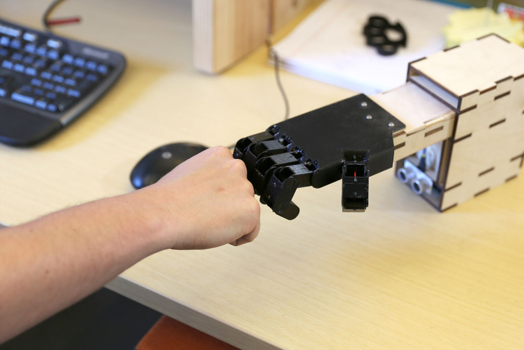
This simple device sits on your desk at work, ready to give you fist bumps throughout the day as you need them. A 3D printed “fist” is moved by a servo attached to a rack and pinion mechanism. An ultrasonic range finder detects when you place your hand near it, and an Arduino Uno controls it all.
Materials:
- Arduino Uno – RadioShack 276 128
- Standard servo – RadioShack 273 766
- Ultrasonic range sensor – RadioShack 276 342
- Misc wires and connectors
- 9V battery connector –RadioShack 270 324
- 9V battery – RadioShack 230 2209
- Slide switch – RadioShack 275 401
- Afinia 3D printer – RadioShack 277 224
- 3D print filament (ABS or PLA) – RadioShack 277 182 or RadioShack 277 163
- Nuts and bolts – RadioShack 640 3018 and RadioShack 640 3011
- ¼” plywood (14″ x 25″)
- Wood glue (optional)
- Rough sandpaper (I used 275 grit)
- Weights (I used misc washers)
- String/wire cable
Step 1: Make cables
To connect the electronics, a few cables are needed. First, make a pair of “splitters” for providing power (5V) and GND to the sensor and servo from the Arduino using female connectors. Since both devices need the same Vcc, the splitters make the wiring easier to put together and more compact when it is assembled.
Next, solder a cable to connect to the ultrasonic range sensor. Use a female connector for the end that the sensor will plug into, and solder the other ends of the wires to individual male headers.
Finally, cut off the female connector at the end of the servo and solder the wires to individual male headers as well.
For more detail: Desktop Fist Bumper using arudino
- What moves the 3D printed fist?
A standard servo attached to a rack and pinion mechanism moves the 3D printed fist. - How does the device detect a hand?
An ultrasonic range sensor detects when a hand is placed near the device. - What microcontroller controls the project?
An Arduino Uno controls the sensor and servo. - How is power supplied to the device?
Power is supplied by a 9V battery connected via a 9V battery connector and controlled with a slide switch. - How are the sensor and servo powered from the Arduino?
Splitter cables are made to provide shared 5V and GND from the Arduino to both the sensor and the servo. - Do you need to modify connectors on the servo and sensor cables?
Yes; the guide suggests cutting off the servo's female connector and soldering wires to male headers, and making a cable for the ultrasonic sensor with a female connector on one end and male headers on the other. - What materials are used for the base and finishing?
The base uses 1/4 inch plywood, optional wood glue, and rough sandpaper (275 grit) for finishing. - Is a 3D printer required for this project?
Yes; a 3D printer (Afinia) and filament (ABS or PLA) are used to print the fist and possibly other parts.