Summary of Microcontroller Projects: Fridge Temperature and Humidity Indicator
This article details a wireless fridge temperature and humidity monitoring system using RF transmission. The transmitter unit, powered by an ATmega328P microcontroller and AM2302 sensor, sends data via a 433MHz module to a receiver unit equipped with another ATmega328P, a 433MHz receiver, and an LCD display. This setup ensures accurate readings without the interference caused by opening the fridge door, featuring low-power consumption design and a signal validity counter.
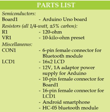
Parts used in the Fridge Temperature and Humidity Indicator:
- ATmega328P microcontroller (IC1) with Arduino Uno bootloader
- AM2302 digital temperature and humidity sensor
- 433MHz transmitter module
- 5V zener diode (ZD1)
- 3.3V zener diode (ZD2)
- 330-ohm resistor (R3)
- 100-ohm resistor (R4)
- 7805 voltage regulator (IC3)
- 16×2 LCD character module display
- 433MHz receiver module
- Switch S2
We can measure temperature and humidity inside the fridge using a normal temperature-humidity indicator but relative humidity (RH) could be inaccurate in that case. The moment the fridge door is opened, RH will shoot up due to ingress or egress of moisture in the surroundings.
The small sniffer device, described in this article, picks up temperature and humidity from inside the fridge and transmits on an RF link to a nearby receiver unit. The receiver unit checks the received code, identifies the right sniffer device and displays live temperature and humidity. Author’s prototype is shown in Fig. 1.
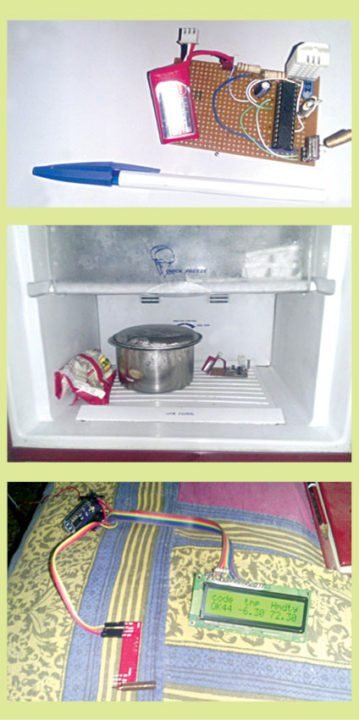
Author’s Prototype
Circuit and working of Fridge Temperature and Humidity Indicator
Circuit diagram of the transmitter unit is shown in Fig. 2. It is built around ATmega328P microcontroller (MCU) (IC1) with Arduino Uno bootloader, AM2302 digital temperature and humidity sensor connected as SENSOR1 to CON1, 433MHz transmitter (TX1), 5V zener ZD1, 3.3V zener ZD2 and a few other components.
Low power consumption of the transmitter is the essence for long operating hours of the gadget. For that, the conventional regulator is replaced by 5V and 3.3V zener diodes, with 330-ohm resistor R3 and 100-ohm resistor R4 in series to reduce current consumption.
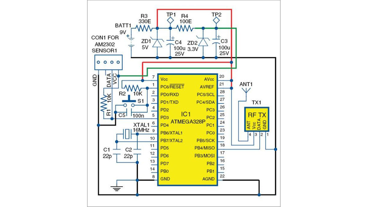
Circuit diagram of the transmitter unit
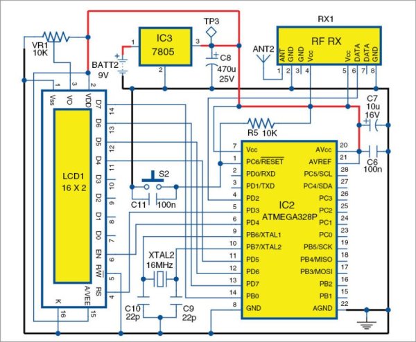
Circuit diagram of the receiver unit
Circuit diagram of the receiver unit is shown in Fig. 3. It is built around another ATmega328P MCU (IC2) with Arduino Uno bootloader, voltage regulator 7805 (IC3), 16×2 LCD character module display (LCD1), 433MHz receiver (RX1) and a few other components. The receiver checks the code word sent by the transmitter unit and displays temperature and humidity on the LCD.
If the transmitter stalls or its power supply gets interrupted, there is no way for the receiver to know whether the incoming signal is valid. To circumvent this problem, a counter has been provided on the left side of the LCD display. If the counter does not move, or stops, it means that the incoming signal has stalled. Reset the system by pressing switch S2 momentarily to come back to normal operation.

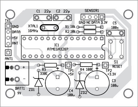
Component layout of the PCB shown in Fig. 4
Component layout of the PCB shown in Fig. 4
Software
The software includes Adafruit library for DHT sensors, virtual wire library for communicating with 433MHz RF sensors and liquid crystal library for the LCD display.
Download source code: click here
Construction and testing
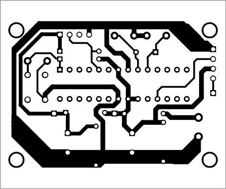
An actual-size, single-side PCB of the transmitter unit is shown in Fig. 4 and its component layout in Fig. 5. An actual-size, single-side PCB of the receiver unit is shown in Fig. 6 and its component layout in Fig. 7.
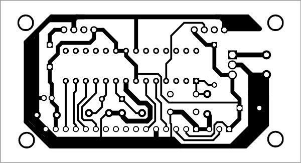
Actual-size PCB pattern of the receiver unit
Component layout of the PCB shown in Fig. 6
Connect the battery of the transmitter and then place the transmitter at a suitable location inside the fridge. Close the fridge door and power on the receiver unit. Temperature and RH will be shown on the LCD. Move the receiver unit to the farthest corner of the house and, in most likelihood, you will still be able to see the temperature and RH ticking.
Read More Detail :Microcontroller Projects: Fridge Temperature and Humidity Indicator
- Why is a normal indicator inaccurate for relative humidity?
Relative humidity readings become inaccurate because they shoot up immediately when the fridge door opens due to moisture ingress or egress. - How does the device prevent high current consumption?
The conventional regulator is replaced by 5V and 3.3V zener diodes connected in series with specific resistors to reduce current flow. - What happens if the transmitter stalls or loses power?
The receiver cannot validate the incoming signal, so a counter on the LCD will stop moving to indicate the stall. - How can you reset the system if the signal stops?
You must press switch S2 momentarily to reset the system and return to normal operation. - Which libraries are required for the software implementation?
The software requires the Adafruit library for DHT sensors, the virtual wire library for 433MHz RF communication, and the liquid crystal library. - Can the receiver unit operate from far away inside the house?
Yes, moving the receiver to the farthest corner of the house usually still allows the user to see the temperature and RH ticking. - What component identifies the correct sniffer device at the receiver?
The receiver unit checks the received code word to identify the right sniffer device before displaying the data. - What type of PCB is recommended for construction?
An actual-size, single-side PCB is used for both the transmitter and receiver units.