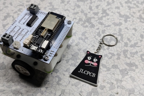
So this is my microbot V1 which is an ESP32 based robot which is powered by a Wemos d32 pro and controlled by Blynk. Its body is a 3D printed square surface that has mounting holes for the same size PCB which is mounted with this setup in the sandwich config to hold the battery in middle.
Electronics Components are mounted on top and bottom part holds Motor and battery, I prepared this bot in such a way that anyone can make this with STL files and PCB file provided!
also, the goal was to make a small Micro Motor Robot that can be controlled via WIFI but using ESP32 is definitely an overkill.
Version 2 will be powered by an ESP8266 (esp12F module) so stay tuned for that!
Supplies
These are the stuff that is required for this built!
- Custom PCB (provided by JLCPCB)
- Wemos D32 Pro
- L293D
- Ams1117
- Cap 20uf 1206
- Cap 2uf 1206
- Battery Connectors
- Female Header pins
- LEDs 0603
- 2Ohms 0805
- Gear DC Motors
- Wheels for Micro Gear Motor
- Caster wheels
- Li-ion battery with a BMS
3D Printed Parts-
- Motor Mounting Brackets
- supporting pillars
- Base
Step 1: ASSEMBLY PROCESS

the assembly process includes a lower base assembly, PCB assembly, and merging of Lower Base with assembled PCB Board.
Check out the project video for a better tutorial!
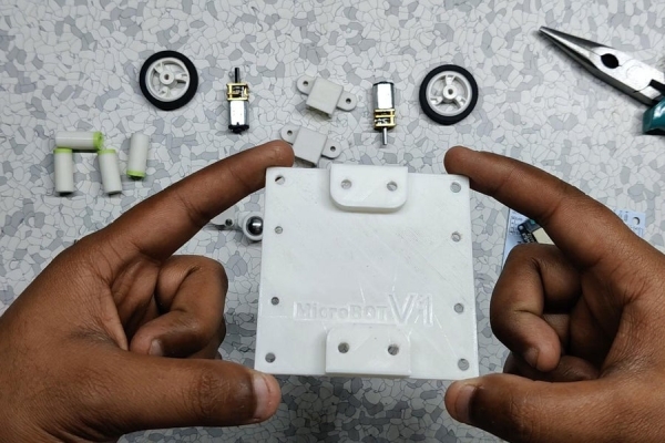
First, I prepared the lower base which includes a 3D printed Base structure, Two Motor Mounts, Micromotor wheels, and caster wheels.
I added the Gear Motor to Motor Mounts and screw them on the Base structure.
after that, I added caster wheels on both sides of the base, this will keep the robot straight and sturdy while moving as this robot is powered by two gear motors, and doesn’t have a balancing feature so, without caster wheels, this robot will lean forward and collapse.
the end result of this assembly process was a sturdy nice base which has two motors on each side, front and back have caster wheels.
after this, I prepared the upper part of the robot which is the ESP32 Breakout board with L293D and other stuff.
Step 2: Preparing the ESP32 Motor Board

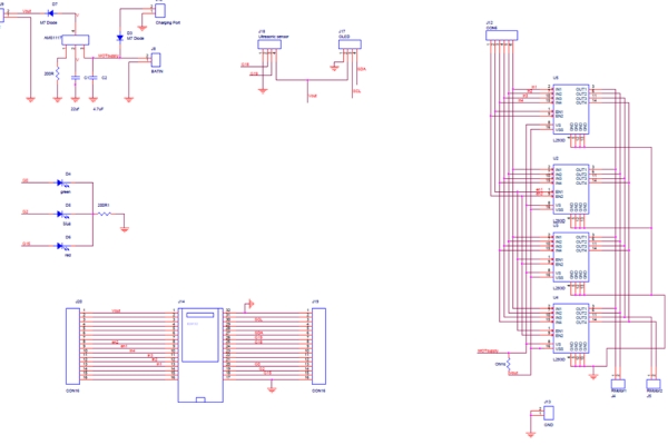
The PCB that I’m using in this project is this ESP32 Motor Board which is basically a Breakout Board for WEMOS D32 Pro ESP32 Board and L293D Motor Driver (4 L293Ds are connected in Parallel so we can get 2.4A Output current)
Schematic is added and as you can see in it, ESP32 Board is connected with the L293D which is in the parallel config and 12V output is step downed by AMS1117 Circuit which bucks down the 12V into 3.3V for ESP32.
you can check out its video for a better tutorial!
I first added the AMS1117 circuit on it and three led with soldering iron, and then tested the voltage regulator by connecting a multimeter at its output and GND and supply 12V to it.
AMS1117 circuit includes two SMD Caps of value 220uf and 20uf at input and output of the voltage regulator and an M7 diode for dropping output voltage a little bit. After getting the step-down voltage, I added the through-hole components like the Motor Driver IC, connectors, and the MCU on the Motor Driver Board and this setup is now ready to be merged with its lower part.
Step 3: Final Assembly!
For the final assembly which is “the merging of the Lower part with the upper part“, I used long M3 Screws and nuts with the mounting pillar in between to connect the TOP PCB with the Assembled lower base.
And the final form of this project is almost ready, it’s pretty much final as we need to add wires to the motors in the right polarity and connect them with the wire connector of PCB.
after connecting the wire, the ROBOT IS COMPLETE! I upload a Basic Demo code for Testing the motor driver setup.
Step 4: Blynk Setup

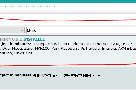
I first installed the Blynk library in Arduino IDE from the library manager by searching the term Blynk.
check out this Blynk Library installation process
http://help.blynk.cc/en/articles/512105-how-to-ins…
After setting up Blynk library in Arduino IDE, I downloaded the Blynk app and setup 6 buttons for controlling each motor driver input and two enable pins for enabling two motors.
For controlling Motor A, two buttons will send a high signal on GPIO13 and 12, also the enable pin will be connected to gpio26 with a switch button.
The same is for Motor B, two buttons will send a HIGH signal on GPIO 25 and 27, Enable B is connected with pin 13. Blynk sends an Auth code which links your setup with this app through WIFI, this auth code is sent by Blynk when you created any project in your logged-in email address. copy that auth code and paste it into the ESP32_WIFI sketch along with your network SSID and Password.
Select the right Board and hit upload and that’s pretty much it.
Step 5: Test RUN!
Watch the video for the whole built process and test run.
Source: MicroBot V1
