Hello and welcome back to another Instructable. In the previous two Instructables, I have shown you how I created PCB coils in Kicad using a Python script, covered the basics of an H bridge, and showed you how I will be using them to control the segments of the 7-segment mechanical display. Make sure you check those out. My aim is to replace the huge electromagnets in the Mechanical 7-segment Display with the PCB coils.
In this Instructable, I will combine the 7 coils and the H bridge drivers on a single PCB to create a working 7 segment display. Let’s get started!
Step 1: Things You Will Need
1x Arduino
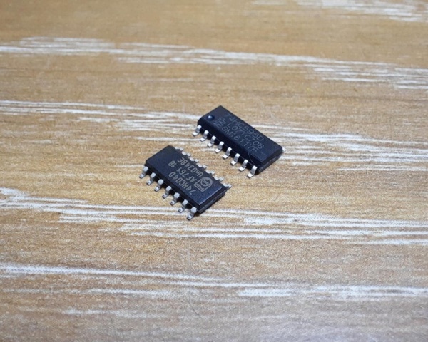
7x DRV8837 H-Bridge Driver IC
2x 74HC04 NOT Gate IC
1x 74HC595 8-bit Shift Register IC
7x Neodymium Magnets 6mm x 1.5mm
4x M3 Screws
Tools:
3D Printer
Step 2: The Plan
The plan is very simple. I will be just combining whatever I have shown in the previous two Instructables into one project. The first step is to design a circuit and PCB in KiCad with 7 coils along with 7 H-bridges to drive the coils. The next step is to design and 3D print the body with the segments. Arduino will be used to control the display.
Step 3: Designing the PCB
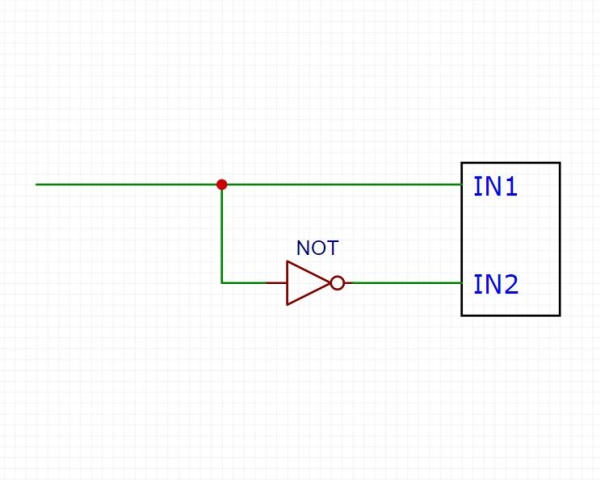
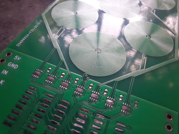
As mentioned in the previous Instructable, I will be using DRV8837 H-bridge driver to control the segments. The driver requires two inputs from a microcontroller to control one segment and 14 inputs for a complete display (7 segments). Since the two inputs are always complemented of each other i.e. if IN1 is HIGH then IN2 is LOW and vice versa, instead of giving two separate inputs, we could directly send a signal (1 or 0) to one input while the other input is given after being passed through a NOT gate which inverts it. In this way, we can control the segment/coil using only one input same as a normal 7 segment display. I will be using 74HC04 IC which has 6 NOT gates in a single package. This arrangement will require 7 I/O pins on the Arduino for a single display. Since a single digit is not much of a use, I will be using at least 4 such digits to display something useful. This means a total of 28 I/O pins will be required. That’s a lot!
Shift register to the rescue! You can drive many digits using shift registers and just 3 I/O pins on the Arduino. You can read more about the shift register and it’s working in my older Instructable. I will be using the 74HC595 8-bit shift register.
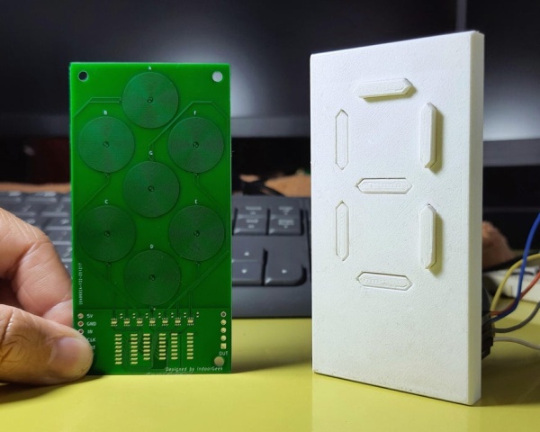
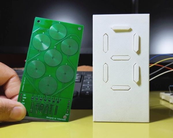
I had found that a coil with 30 turns and 4 layers is suitable for my need. I arranged the coils as close as possible in order to make the display smaller. This method of making coils in KiCad makes the software a bit laggy (at least for me) if there are many coils.
You can find the Gerber files for the PCB here. I ordered my PCBs along with the stencil from JLCPCB.
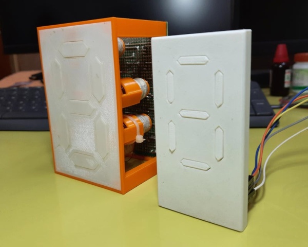
Step 4: Preparing the Body
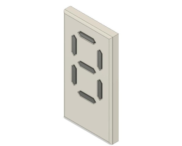
I designed the body in Fusion 360 and printed it using Ender 3. I have attached the STL files below.
You need to print:
- 1x Face
- 7x Segment
There is adequate spacing between the segments and the face to ensure free movement of the segments. Depending on the print results, it might require some sanding.
Each segment has a slot to accommodate a 6 x 1.5 mm disc neodymium magnet. Make sure that the magnetic pole created by the coil on the front side is the same as the pole of the magnet which is facing the coil. In simple words, insert the magnet in the segment in such a way that the coil repels the segment. Use super glue to secure the magnet in place.
Note: I will refer to the side on which components are present as the ‘Back’ side of the PCB.
Step 5: Putting Things Together
Once I received the PCBs from JLCPCB, I soldered the SMT components on the PCB using reflow soldering that too with a clothing iron! The tiny H-bridges were quite tricky but everything went well. I still need to work on my stenciling skills.
Solder a 5 pin male header for sending power and data to the display.
Place the segments in their position. Ensure free movement of the segments before closing the back with the PCB. Secure the PCB to the body using M3 screws.
Step 6: Time for Code
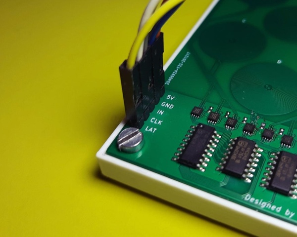
You can use any Arduino of your choice. I will be using Nano in this project. Connect the Arduino to the display as shown below:
LAT – D8
CLK – D12
IN – D11
GND – GND
The sketch file has been attached. Download and open it using Arduino IDE. There is nothing special in the code.
The bytes are stored in an array (digit[]). The bits are sent serially to a shift register which then ‘shifts out’ the bits parallelly. The bits are arranged in the following manner:
A B C D E F G
If you want to display number 1, then segments B and C should be ON while the remaining should be OFF. So, the byte to be sent to display number 1 is ‘01100000’. The last bit should always be 0 since we have 7 segments and a byte has 8 bits.
Step 7: Enjoy!
Make sure there are no shorts before powering up the display.
Use an external 5V power supply (capable of supplying at least 2A) to power the display. Make sure you connect the GND of Arduino and power supply together.
And it works as expected!
As you can see, there is a considerable decrease in the size of the display. The current drawn by the entire display is around 650mA. This is a huge reduction considering that the old display needed over 1A just for one segment!
Step 8: What’s Next?
I will do some modifications to the PCB design and make it even smaller.
Improve the 3D design. \
And make at least 4 such digits, connect it to the internet and display something useful data. That would be fun!
Thank you for sticking to the end. I hope you all love this project. If you did, please make sure you subscribe to my YouTube channel for more such projects.
Source: Mechanical 7 Segment Display V2