Hello all! This instructable happens to be part 3 of my ESP series where I continue to experiment and explore the various features of the ESP 8266-01 board. In the first and second part of the series I have mentioned the wonderful capability of this little board to support I2C communication and also interfaced the ESP board with multiple I2C devices.
You can read more about these features in the previous parts:
Part 1: https://www.instructables.com/I2C-With-the-ESP8266…
Part 2: https://www.instructables.com/ESP8266-01-With-Mult…
In this part of the series, we will look at the possibility of extending the GPIO pins of the ESP8266 and also control the pins using IoT!
For IoT integration we will be using the Blynk application which is quite simple to integrate with IoT projects.
Let’s get ahead with this instructable!
Step 1: The GPIO Expander
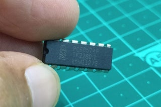
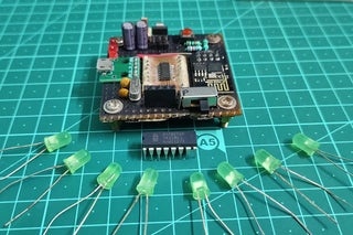
The PCF8574 is a very popular I2C based GPIO expander which has 2 pins to control the I2C address and 8 GPIO pins which of course can either be configured as input or output. This is also the chip which is used in the 16 by 2 LCD modules that are connected via I2C.
Since we know that the ESP8266 module supports I2C, this chip is a perfect choice to extend the GPIO of my ESP-O-One board.
In case you are wondering, what this ESP-O-One board is, it is my custom made development board for ESP8266 01 WiFi module.
You can check more about this custom board in this instructable: https://www.instructables.com/ESP-O-One-Making-You…
Coming back to the chip, you have 3 pins A0,A1 and A2 which can be used to set the I2C address of the specific chip. Since the chip comes with programmable address feature, we can basically daisy chain a total of 8 such chips based on the voltage provided to the 3 pins and we can get a whopping 64 GPIO pins which can be individually accessed via I2C.
I have also attached the datasheet of this chip for your ready reference
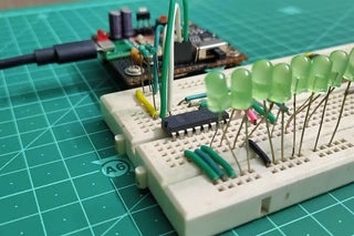
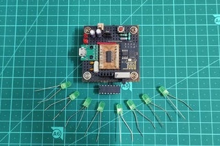
Step 2: Making the First Circuit: LED Pattern
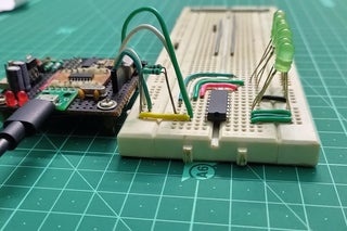
With the basics of the I2C based I/O expander discussed in the previous step. It is now time to test the theory and hook up some LEDs to the 8 I/O pins of the IC. Naturally all of these 8 pins will be declared as output since they will be toggling the LEDs.
So we make our basic connections on the breadboard and hook up 10K pull up resistors to SDA and SCL pins of the IC.
My breadboard setup turned out to be pretty neat because I was saved from the hassle of wiring the ESP 8266 all because of the ESP-O-One board I made, that has direct accessible pins for Vcc, Ground, GPIO 0 and GPIO2.
Step 3: Coding the Sequence
For the first experiment, we will be blinking the 8 LEDs connected to the I/O ports in a sequential manner.
The code for this can be simplified into the following steps:
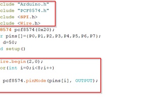
- Initialising the PCF8574 and the Wire Library
- Declaring all the 8 pins as output.
- Creating a function to sequentially blink LED and calling it continuously in the loop function.
The PCF8574 can be implemented so easily thanks to the simplified library that we can get online thanks to a vast online community.
The link to the library: https://github.com/xreef/PCF8574_library
Now as the pins are labelled P0, P1 and so on instead of just numerical style, I have declared the pins in an array and used a for loop to configure each pin as output. This method saves a lot of repetitive coding for the same purpose. Next, we declare assign the I2C address with his 0x20 in hexadecimal as A0, A1 and A2 are grounded in our case. You can refer to the chart in the previous step to get the idea about the addresses.
Next the GPIO 0 and GPIO 2 pins are declared as SCK and SDA in the Wire.begin() function.
The loop section is pretty simple, it calls the said pattern endlessly toggling each pins of the PCF8574 to give us our desired pattern.
The code along with few other patterns is attached in this step.
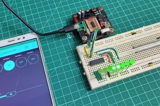
Step 4: Next Up: Adding the IoT Feature
It was quite interesting to see the LED sequence being beautifully displayed via the ESP board. The next step is to include the IoT feature to our project. For this we will be using the Blynk IoT platform as it is very easy to use and integrate with projects including the the ESP and Arduino boards.
The plan here is to use the slider feature on the Blynk application to control the delay or speed at which the LED pattern is working. Changing the slider position correspondingly changes the pattern speed.
The code here can be broken down to the following steps:
- Importing the Blynk libraries
- Giving the WiFi credentials and Authentication token
- Initialising the Blynk.run() function and using virtual pin connected to slider as a input
- Manipulating the delay using the value returned by slider position.
After creating the project on Blynk application, we initialise a slider feature which is linked to virtual pin 0 and returns values from range 0 to 5.
We define the blynk.write() function to read the number returned by the V0 pin. This function is internally called by the Blunk.run() fucntion so it has been defined outside the loop function.
Now based on the slider position we use a series of if else statement to change the delay of the pattern.
You are free to use my code and understand the working.
Step 5: Adding More Features
I was able to successfully control the speed to the LED pattern via the blynk application. The next thing in mind was to control the speed as well as toggle the different patterns using the app.
The idea here is to use 4 buttons to toggle between 4 different patterns and the slider to control the speed at which the patterns are displayed.
So the code can be broken down pretty much to the last code,only assition would be the logic for buttons
- Assigning a virtual pin to each of the buttons
- using the blynk.write() for each virtual pin to change the value of a variable.
- In the loop section, check the value of this variable and call the respective function
The code is as usual attached to understand the concept
Step 6: Conclusion
It was a successful project in terms of implementing IoT on ESP 8266 and also expanding the GPIOs using the popular PCF8574 IC.
I hope you like this instructable series on exploring and experimenting with the hidden features of the ESP8266.
Feel free to share your feedbacks and suggestions in the comment section and I hope this article was helpful for you.
Till then, see you in the next instructable!
Source: