Summary of Measuring Battery Capacity With an Arduino
The author built an Arduino-based device to compare battery capacities since packaging lacks energy indicators. The circuit discharges batteries through a resistive load, measuring voltage and temperature while logging data via USB. This project provides relative comparisons of different battery brands under similar loads.
Parts used in Measuring Battery Capacity With an Arduino:
- Arduino
- LCD panel
- Temperature sensor
- USB logging capability
- Resistive load (4 x 22R resistors in parallel)
- Adafruit case with cutouts and standoffs
- Stripboard
I needed a couple of AA batteries and found the display at the supermarket where they were all arrayed. Normally when I’m shopping in the supermarket, I tend to look at the price/kg or price/l when comparing similar products. In the case of the batteries, there was no such indicator. Fine, I thought, I’ll work it out myself. I grabbed a few different makes and scanned the packaging for some measure of their capacity. Nothing. Not a single one of the batteries had any indicator of how much energy they would provide. Instead, they all had terms like ‘PLUS’, ‘SUPER’, ‘ULTRA’ and of course had wildly differing prices. So, I decided that it was time for an experiment and bought one pack of every type I could find.

The Plan
My idea was really simple: I would make a circuit that would fully discharge each of the batteries while measuring how much energy it produced (displayed in Joules and in Watt-Hours. I had an Arduino and an LCD panel left over from a different project so I thought I’d make a standalone unit. As the design evolved, I let two additional features creep in:
- Add a temperature sensor to track ambient temperature during the test since that certainly affects battery capacity.
- Add a USB logging capability so that I could capture all the data to plot terminal voltage as the battery discharges.
Note: This was never intended to be a scientific instrument to measure how long a battery would power your circuit – it’s designed to provide a relative comparison of different batteries using a similar load.
The Design
The circuit works by measuring the voltage across a fixed load every second until the voltage drops to less than 0.2V. For simplicity, I used a resistive load (the original plan was to use a 4.7R resistor but I didn’t have any high power resistors to hand so I used 4 22R resistors in parallel instead giving me an effective load of 5.5R. Here’s the final circuit:
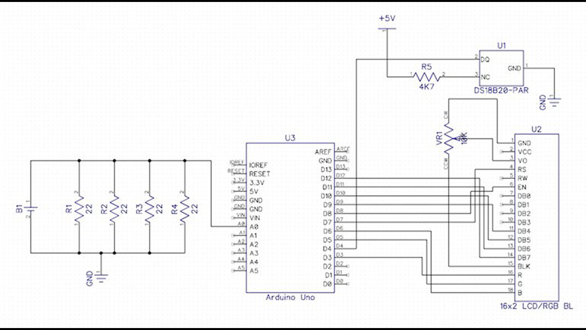
This case from adafruit ended up being perfect because it already has cutouts and standoffs for the arduino and the LCD. All that was left was to add a little bit of stripboard to hold the extra components. Note that the whole circuit is powered from the USB connection (or the DC jack) – all the power from the battery is consumed by the load resistors.
For more detail: Measuring Battery Capacity With an Arduino
- Why did the author conduct this experiment?
Battery packaging lacked energy capacity indicators despite having terms like PLUS or SUPER. - How does the circuit measure battery discharge?
It measures voltage across a fixed load every second until voltage drops below 0.2V. - What components were added to track environmental factors?
A temperature sensor was added to track ambient temperature during testing. - How is data captured from the test?
USB logging capability captures all data to plot terminal voltage as the battery discharges. - What type of load was used in the final design?
Four 22R resistors connected in parallel created an effective load of 5.5R. - Where does the circuit get its power?
The whole circuit is powered from the USB connection or the DC jack. - What units are displayed for energy production?
The display shows energy in Joules and in Watt-Hours. - Is this device intended for scientific precision?
No, it is designed to provide a relative comparison using a similar load.