Summary of Master the Art of Bootloader Burning with Arduino as ISP: A Comprehensive Guide
Summary: This article explains how to use an Arduino as an In-System Programmer (ISP) to flash bootloaders onto AVR microcontrollers. It covers required hardware, loading the ArduinoISP sketch, wiring SPI and reset pins, installing Arduino IDE and cores (e.g., MiniCore), burning the bootloader, and testing the target MCU by uploading a Blink sketch via USB-TTL. The provided ArduinoISP code and step-by-step procedures enable beginners to program AVRs without dedicated programmers.
Parts used in the Arduino as ISP Bootloader:
- Arduino UNO
- PU DIP IC Microcontroller ATMEGA8A
- Crystal 16 MHz
- Push Button 6x6x4.3
- LED Red
- Ceramic Capacitor 22PF
- Electrolytic Capacitor 10 uF
- Resistor 10KΩ
- Breadboard
- Jumper Wires
Introduction
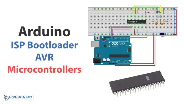
For many electronics projects, AVR microcontrollers are commonly used. However, as a beginner, uploading or flashing code to an AVR can be challenging to understand. When other programming hardware is unavailable, an Arduino board can help burn bootloaders onto AVRs. It also enables creating and testing AVR programs. Therefore, this article will demonstrate using an Arduino as an In-System Programmer (ISP) to flash bootloaders on AVR microcontrollers.
Flashing the bootloader requires connecting the Arduino to the target AVR microcontroller via specific pins. The process and pin connections are detailed. Step-by-step instructions are provided to carry out the bootloader flashing. Let’s get started with exploring how to do this! Details on connecting the boards and executing the flashing procedure are contained within to walk through the process.
Arduino as ISP Bootloader?
Arduino boards have the ability to function as an In-System Programmer (ISP) for flashing bootloaders onto AVR microcontrollers. A bootloader is a small start-up program that enables programming the microcontroller over a serial connection without requiring external hardware.
To leverage the Arduino as an ISP, the ArduinoISP sketch must be loaded onto the Arduino board first. This sketch endows the Arduino with the necessary firmware to operate as an ISP. Once programmed with ArduinoISP, the Arduino IDE can be used to install bootloaders on the target AVR microcontroller.
Specifically, the ArduinoISP sketch provides the programming software transfers the bootloader from the Arduino to the AVR. This allows taking advantage of the Arduino’s programming capabilities to flash bootloaders without any other dedicated hardware.
Hardware Components
Certain hardware is needed to utilize an Arduino as an In-System Programmer (ISP) for burning bootloaders onto AVR microcontrollers. Specifically, the required components are:
| S.no | Component | Value | Qty |
|---|---|---|---|
| 1. | Arduino UNO | – | 1 |
| 2. | PU DIP IC Microcontroller | ATMEGA8A | 1 |
| 3. | Crystal | 16 MHz | 1 |
| 4. | Push Button | 6x6x4.3 | 1 |
| 5. | LED | Red | 1 |
| 6. | Ceramic Capacitor | 22PF | 1 |
| 7. | Electrolytic Capacitor | 10 uF | 1 |
| 8. | Resistor | 10KΩ | 1 |
| 9. | Breadboard | – | 1 |
| 10. | Jumper Wires | – | 1 |
Arduino ISP Bootloader
To use Arduino as an ISP to burn a bootloader on an AVR microcontroller, you need to follow the given steps:
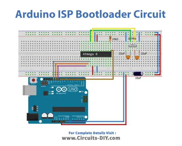
Schematic
Make connections according to the circuit diagram given below.
Installing Arduino IDE
The first step is to install the Arduino IDE software from the official Arduino website. Properly downloading and setting up the Arduino development environment is crucial. A simple guide on “How to install Arduino IDE” is provided below to walk through the installation process step-by-step.
Installing Libraries
Prior to uploading code, download and extract several libraries to the Arduino library folder location. These libraries are required to interface various sensors with the Arduino board.
Specifically, download and unzip the following libraries to C:\Program Files (x86)\Arduino\libraries:
Wire
Dallas Temperature
LiquidCrystal
DHT
A quick guide titled “How to Add Libraries in Arduino IDE” is provided to walk through the simple steps for installing libraries into the Arduino development environment. Having the proper libraries installed upfront will enable sensor communication and functionality within programs.
Code
Now copy the following code and upload it to Arduino IDE Software.
/*
  Made on 18 may 2021
  Home
  based on Arduino Library
*/
// ArduinoISP
// Copyright (c) 2008-2011 Randall Bohn
// If you require a license, see
// http://www.opensource.org/licenses/bsd-license.php
//
// This sketch turns the Arduino into a AVRISP using the following Arduino pins:
//
// Pin 10 is used to reset the target microcontroller.
//
// By default, the hardware SPI pins MISO, MOSI and SCK are used to communicate
// with the target. On all Arduinos, these pins can be found
// on the ICSP/SPI header:
//
//               MISO °. . 5V (!) Avoid this pin on Due, Zero...
//               SCK   . . MOSI
//                     . . GND
//
// On some Arduinos (Uno,...), pins MOSI, MISO and SCK are the same pins as
// digital pin 11, 12 and 13, respectively. That is why many tutorials instruct
// you to hook up the target to these pins. If you find this wiring more
// practical, have a define USE_OLD_STYLE_WIRING. This will work even when not
// using an Uno. (On an Uno this is not needed).
//
// Alternatively you can use any other digital pin by configuring
// software ('BitBanged') SPI and having appropriate defines for PIN_MOSI,
// PIN_MISO and PIN_SCK.
//
// IMPORTANT: When using an Arduino that is not 5V tolerant (Due, Zero, ...) as
// the programmer, make sure to not expose any of the programmer's pins to 5V.
// A simple way to accomplish this is to power the complete system (programmer
// and target) at 3V3.
//
// Put an LED (with resistor) on the following pins:
// 9: Heartbeat   - shows the programmer is running
// 8: Error       - Lights up if something goes wrong (use red if that makes sense)
// 7: Programming - In communication with the slave
//

#include "Arduino.h"
#undef SERIAL


#define PROG_FLICKER true

// Configure SPI clock (in Hz).
// E.g. for an ATtiny @ 128 kHz: the datasheet states that both the high and low
// SPI clock pulse must be > 2 CPU cycles, so take 3 cycles i.e. divide target
// f_cpu by 6:
//     #define SPI_CLOCK            (128000/6)
//
// A clock slow enough for an ATtiny85 @ 1 MHz, is a reasonable default:

#define SPI_CLOCK 		(1000000/6)


// Select hardware or software SPI, depending on SPI clock.
// Currently only for AVR, for other architectures (Due, Zero,...), hardware SPI
// is probably too fast anyway.

#if defined(ARDUINO_ARCH_AVR)

#if SPI_CLOCK > (F_CPU / 128)
#define USE_HARDWARE_SPI
#endif

#endif

// Configure which pins to use:

// The standard pin configuration.
#ifndef ARDUINO_HOODLOADER2

#define RESET     10 // Use pin 10 to reset the target rather than SS
#define LED_HB    9
#define LED_ERR   8
#define LED_PMODE 7

// Uncomment following line to use the old Uno style wiring
// (using pin 11, 12 and 13 instead of the SPI header) on Leonardo, Due...

// #define USE_OLD_STYLE_WIRING

#ifdef USE_OLD_STYLE_WIRING

#define PIN_MOSI	11
#define PIN_MISO	12
#define PIN_SCK		13

#endif

// HOODLOADER2 means running sketches on the ATmega16U2 serial converter chips
// on Uno or Mega boards. We must use pins that are broken out:
#else

#define RESET     	4
#define LED_HB    	7
#define LED_ERR   	6
#define LED_PMODE 	5

#endif

// By default, use hardware SPI pins:
#ifndef PIN_MOSI
#define PIN_MOSI 	MOSI
#endif

#ifndef PIN_MISO
#define PIN_MISO 	MISO
#endif

#ifndef PIN_SCK
#define PIN_SCK 	SCK
#endif

// Force bitbanged SPI if not using the hardware SPI pins:
#if (PIN_MISO != MISO) ||  (PIN_MOSI != MOSI) || (PIN_SCK != SCK)
#undef USE_HARDWARE_SPI
#endif


// Configure the serial port to use.
//
// Prefer the USB virtual serial port (aka. native USB port), if the Arduino has one:
//   - it does not autoreset (except for the magic baud rate of 1200).
//   - it is more reliable because of USB handshaking.
//
// Leonardo and similar have an USB virtual serial port: 'Serial'.
// Due and Zero have an USB virtual serial port: 'SerialUSB'.
//
// On the Due and Zero, 'Serial' can be used too, provided you disable autoreset.
// To use 'Serial': #define SERIAL Serial

#ifdef SERIAL_PORT_USBVIRTUAL
#define SERIAL SERIAL_PORT_USBVIRTUAL
#else
#define SERIAL Serial
#endif


// Configure the baud rate:

#define BAUDRATE	19200
// #define BAUDRATE	115200
// #define BAUDRATE	1000000


#define HWVER 2
#define SWMAJ 1
#define SWMIN 18

// STK Definitions
#define STK_OK      0x10
#define STK_FAILED  0x11
#define STK_UNKNOWN 0x12
#define STK_INSYNC  0x14
#define STK_NOSYNC  0x15
#define CRC_EOP     0x20 //ok it is a space...

void pulse(int pin, int times);

#ifdef USE_HARDWARE_SPI
#include "SPI.h"
#else

#define SPI_MODE0 0x00

class SPISettings {
  public:
    // clock is in Hz
    SPISettings(uint32_t clock, uint8_t bitOrder, uint8_t dataMode) : clock(clock) {
      (void) bitOrder;
      (void) dataMode;
    };

  private:
    uint32_t clock;

    friend class BitBangedSPI;
};

class BitBangedSPI {
  public:
    void begin() {
      digitalWrite(PIN_SCK, LOW);
      digitalWrite(PIN_MOSI, LOW);
      pinMode(PIN_SCK, OUTPUT);
      pinMode(PIN_MOSI, OUTPUT);
      pinMode(PIN_MISO, INPUT);
    }

    void beginTransaction(SPISettings settings) {
      pulseWidth = (500000 + settings.clock - 1) / settings.clock;
      if (pulseWidth == 0)
        pulseWidth = 1;
    }

    void end() {}

    uint8_t transfer (uint8_t b) {
      for (unsigned int i = 0; i < 8; ++i) {
        digitalWrite(PIN_MOSI, (b & 0x80) ? HIGH : LOW);
        digitalWrite(PIN_SCK, HIGH);
        delayMicroseconds(pulseWidth);
        b = (b << 1) | digitalRead(PIN_MISO);
        digitalWrite(PIN_SCK, LOW); // slow pulse
        delayMicroseconds(pulseWidth);
      }
      return b;
    }

  private:
    unsigned long pulseWidth; // in microseconds
};

static BitBangedSPI SPI;

#endif

void setup() {
  SERIAL.begin(BAUDRATE);

  pinMode(LED_PMODE, OUTPUT);
  pulse(LED_PMODE, 2);
  pinMode(LED_ERR, OUTPUT);
  pulse(LED_ERR, 2);
  pinMode(LED_HB, OUTPUT);
  pulse(LED_HB, 2);

}

int error = 0;
int pmode = 0;
// address for reading and writing, set by 'U' command
unsigned int here;
uint8_t buff[256]; // global block storage

#define beget16(addr) (*addr * 256 + *(addr+1) )
typedef struct param {
  uint8_t devicecode;
  uint8_t revision;
  uint8_t progtype;
  uint8_t parmode;
  uint8_t polling;
  uint8_t selftimed;
  uint8_t lockbytes;
  uint8_t fusebytes;
  uint8_t flashpoll;
  uint16_t eeprompoll;
  uint16_t pagesize;
  uint16_t eepromsize;
  uint32_t flashsize;
}
parameter;

parameter param;

// this provides a heartbeat on pin 9, so you can tell the software is running.
uint8_t hbval = 128;
int8_t hbdelta = 8;
void heartbeat() {
  static unsigned long last_time = 0;
  unsigned long now = millis();
  if ((now - last_time) < 40)
    return;
  last_time = now;
  if (hbval > 192) hbdelta = -hbdelta;
  if (hbval < 32) hbdelta = -hbdelta;
  hbval += hbdelta;
  analogWrite(LED_HB, hbval);
}

static bool rst_active_high;

void reset_target(bool reset) {
  digitalWrite(RESET, ((reset && rst_active_high) || (!reset && !rst_active_high)) ? HIGH : LOW);
}

void loop(void) {
  // is pmode active?
  if (pmode) {
    digitalWrite(LED_PMODE, HIGH);
  } else {
    digitalWrite(LED_PMODE, LOW);
  }
  // is there an error?
  if (error) {
    digitalWrite(LED_ERR, HIGH);
  } else {
    digitalWrite(LED_ERR, LOW);
  }

  // light the heartbeat LED
  heartbeat();
  if (SERIAL.available()) {
    avrisp();
  }
}

uint8_t getch() {
  while (!SERIAL.available());
  return SERIAL.read();
}
void fill(int n) {
  for (int x = 0; x < n; x++) {
    buff[x] = getch();
  }
}

#define PTIME 30
void pulse(int pin, int times) {
  do {
    digitalWrite(pin, HIGH);
    delay(PTIME);
    digitalWrite(pin, LOW);
    delay(PTIME);
  } while (times--);
}

void prog_lamp(int state) {
  if (PROG_FLICKER) {
    digitalWrite(LED_PMODE, state);
  }
}

uint8_t spi_transaction(uint8_t a, uint8_t b, uint8_t c, uint8_t d) {
  SPI.transfer(a);
  SPI.transfer(b);
  SPI.transfer(c);
  return SPI.transfer(d);
}

void empty_reply() {
  if (CRC_EOP == getch()) {
    SERIAL.print((char)STK_INSYNC);
    SERIAL.print((char)STK_OK);
  } else {
    error++;
    SERIAL.print((char)STK_NOSYNC);
  }
}

void breply(uint8_t b) {
  if (CRC_EOP == getch()) {
    SERIAL.print((char)STK_INSYNC);
    SERIAL.print((char)b);
    SERIAL.print((char)STK_OK);
  } else {
    error++;
    SERIAL.print((char)STK_NOSYNC);
  }
}

void get_version(uint8_t c) {
  switch (c) {
    case 0x80:
      breply(HWVER);
      break;
    case 0x81:
      breply(SWMAJ);
      break;
    case 0x82:
      breply(SWMIN);
      break;
    case 0x93:
      breply('S'); // serial programmer
      break;
    default:
      breply(0);
  }
}

void set_parameters() {
  // call this after reading parameter packet into buff[]
  param.devicecode = buff[0];
  param.revision   = buff[1];
  param.progtype   = buff[2];
  param.parmode    = buff[3];
  param.polling    = buff[4];
  param.selftimed  = buff[5];
  param.lockbytes  = buff[6];
  param.fusebytes  = buff[7];
  param.flashpoll  = buff[8];
  // ignore buff[9] (= buff[8])
  // following are 16 bits (big endian)
  param.eeprompoll = beget16(&buff[10]);
  param.pagesize   = beget16(&buff[12]);
  param.eepromsize = beget16(&buff[14]);

  // 32 bits flashsize (big endian)
  param.flashsize = buff[16] * 0x01000000
                    + buff[17] * 0x00010000
                    + buff[18] * 0x00000100
                    + buff[19];

  // AVR devices have active low reset, AT89Sx are active high
  rst_active_high = (param.devicecode >= 0xe0);
}

void start_pmode() {

  // Reset target before driving PIN_SCK or PIN_MOSI

  // SPI.begin() will configure SS as output, so SPI master mode is selected.
  // We have defined RESET as pin 10, which for many Arduinos is not the SS pin.
  // So we have to configure RESET as output here,
  // (reset_target() first sets the correct level)
  reset_target(true);
  pinMode(RESET, OUTPUT);
  SPI.begin();
  SPI.beginTransaction(SPISettings(SPI_CLOCK, MSBFIRST, SPI_MODE0));

  // See AVR datasheets, chapter "SERIAL_PRG Programming Algorithm":

  // Pulse RESET after PIN_SCK is low:
  digitalWrite(PIN_SCK, LOW);
  delay(20); // discharge PIN_SCK, value arbitrarily chosen
  reset_target(false);
  // Pulse must be minimum 2 target CPU clock cycles so 100 usec is ok for CPU
  // speeds above 20 KHz
  delayMicroseconds(100);
  reset_target(true);

  // Send the enable programming command:
  delay(50); // datasheet: must be > 20 msec
  spi_transaction(0xAC, 0x53, 0x00, 0x00);
  pmode = 1;
}

void end_pmode() {
  SPI.end();
  // We're about to take the target out of reset so configure SPI pins as input
  pinMode(PIN_MOSI, INPUT);
  pinMode(PIN_SCK, INPUT);
  reset_target(false);
  pinMode(RESET, INPUT);
  pmode = 0;
}

void universal() {
  uint8_t ch;

  fill(4);
  ch = spi_transaction(buff[0], buff[1], buff[2], buff[3]);
  breply(ch);
}

void flash(uint8_t hilo, unsigned int addr, uint8_t data) {
  spi_transaction(0x40 + 8 * hilo,
                  addr >> 8 & 0xFF,
                  addr & 0xFF,
                  data);
}
void commit(unsigned int addr) {
  if (PROG_FLICKER) {
    prog_lamp(LOW);
  }
  spi_transaction(0x4C, (addr >> 8) & 0xFF, addr & 0xFF, 0);
  if (PROG_FLICKER) {
    delay(PTIME);
    prog_lamp(HIGH);
  }
}

unsigned int current_page() {
  if (param.pagesize == 32) {
    return here & 0xFFFFFFF0;
  }
  if (param.pagesize == 64) {
    return here & 0xFFFFFFE0;
  }
  if (param.pagesize == 128) {
    return here & 0xFFFFFFC0;
  }
  if (param.pagesize == 256) {
    return here & 0xFFFFFF80;
  }
  return here;
}


void write_flash(int length) {
  fill(length);
  if (CRC_EOP == getch()) {
    SERIAL.print((char) STK_INSYNC);
    SERIAL.print((char) write_flash_pages(length));
  } else {
    error++;
    SERIAL.print((char) STK_NOSYNC);
  }
}

uint8_t write_flash_pages(int length) {
  int x = 0;
  unsigned int page = current_page();
  while (x < length) {
    if (page != current_page()) {
      commit(page);
      page = current_page();
    }
    flash(LOW, here, buff[x++]);
    flash(HIGH, here, buff[x++]);
    here++;
  }

  commit(page);

  return STK_OK;
}

#define EECHUNK (32)
uint8_t write_eeprom(unsigned int length) {
  // here is a word address, get the byte address
  unsigned int start = here * 2;
  unsigned int remaining = length;
  if (length > param.eepromsize) {
    error++;
    return STK_FAILED;
  }
  while (remaining > EECHUNK) {
    write_eeprom_chunk(start, EECHUNK);
    start += EECHUNK;
    remaining -= EECHUNK;
  }
  write_eeprom_chunk(start, remaining);
  return STK_OK;
}
// write (length) bytes, (start) is a byte address
uint8_t write_eeprom_chunk(unsigned int start, unsigned int length) {
  // this writes byte-by-byte, page writing may be faster (4 bytes at a time)
  fill(length);
  prog_lamp(LOW);
  for (unsigned int x = 0; x < length; x++) {
    unsigned int addr = start + x;
    spi_transaction(0xC0, (addr >> 8) & 0xFF, addr & 0xFF, buff[x]);
    delay(45);
  }
  prog_lamp(HIGH);
  return STK_OK;
}

void program_page() {
  char result = (char) STK_FAILED;
  unsigned int length = 256 * getch();
  length += getch();
  char memtype = getch();
  // flash memory @here, (length) bytes
  if (memtype == 'F') {
    write_flash(length);
    return;
  }
  if (memtype == 'E') {
    result = (char)write_eeprom(length);
    if (CRC_EOP == getch()) {
      SERIAL.print((char) STK_INSYNC);
      SERIAL.print(result);
    } else {
      error++;
      SERIAL.print((char) STK_NOSYNC);
    }
    return;
  }
  SERIAL.print((char)STK_FAILED);
  return;
}

uint8_t flash_read(uint8_t hilo, unsigned int addr) {
  return spi_transaction(0x20 + hilo * 8,
                         (addr >> 8) & 0xFF,
                         addr & 0xFF,
                         0);
}

char flash_read_page(int length) {
  for (int x = 0; x < length; x += 2) {
    uint8_t low = flash_read(LOW, here);
    SERIAL.print((char) low);
    uint8_t high = flash_read(HIGH, here);
    SERIAL.print((char) high);
    here++;
  }
  return STK_OK;
}

char eeprom_read_page(int length) {
  // here again we have a word address
  int start = here * 2;
  for (int x = 0; x < length; x++) {
    int addr = start + x;
    uint8_t ee = spi_transaction(0xA0, (addr >> 8) & 0xFF, addr & 0xFF, 0xFF);
    SERIAL.print((char) ee);
  }
  return STK_OK;
}

void read_page() {
  char result = (char)STK_FAILED;
  int length = 256 * getch();
  length += getch();
  char memtype = getch();
  if (CRC_EOP != getch()) {
    error++;
    SERIAL.print((char) STK_NOSYNC);
    return;
  }
  SERIAL.print((char) STK_INSYNC);
  if (memtype == 'F') result = flash_read_page(length);
  if (memtype == 'E') result = eeprom_read_page(length);
  SERIAL.print(result);
}

void read_signature() {
  if (CRC_EOP != getch()) {
    error++;
    SERIAL.print((char) STK_NOSYNC);
    return;
  }
  SERIAL.print((char) STK_INSYNC);
  uint8_t high = spi_transaction(0x30, 0x00, 0x00, 0x00);
  SERIAL.print((char) high);
  uint8_t middle = spi_transaction(0x30, 0x00, 0x01, 0x00);
  SERIAL.print((char) middle);
  uint8_t low = spi_transaction(0x30, 0x00, 0x02, 0x00);
  SERIAL.print((char) low);
  SERIAL.print((char) STK_OK);
}
//////////////////////////////////////////
//////////////////////////////////////////


////////////////////////////////////
////////////////////////////////////
void avrisp() {
  uint8_t ch = getch();
  switch (ch) {
    case '0': // signon
      error = 0;
      empty_reply();
      break;
    case '1':
      if (getch() == CRC_EOP) {
        SERIAL.print((char) STK_INSYNC);
        SERIAL.print("AVR ISP");
        SERIAL.print((char) STK_OK);
      }
      else {
        error++;
        SERIAL.print((char) STK_NOSYNC);
      }
      break;
    case 'A':
      get_version(getch());
      break;
    case 'B':
      fill(20);
      set_parameters();
      empty_reply();
      break;
    case 'E': // extended parameters - ignore for now
      fill(5);
      empty_reply();
      break;
    case 'P':
      if (!pmode)
        start_pmode();
      empty_reply();
      break;
    case 'U': // set address (word)
      here = getch();
      here += 256 * getch();
      empty_reply();
      break;

    case 0x60: //STK_PROG_FLASH
      getch(); // low addr
      getch(); // high addr
      empty_reply();
      break;
    case 0x61: //STK_PROG_DATA
      getch(); // data
      empty_reply();
      break;

    case 0x64: //STK_PROG_PAGE
      program_page();
      break;

    case 0x74: //STK_READ_PAGE 't'
      read_page();
      break;

    case 'V': //0x56
      universal();
      break;
    case 'Q': //0x51
      error = 0;
      end_pmode();
      empty_reply();
      break;

    case 0x75: //STK_READ_SIGN 'u'
      read_signature();
      break;

    // expecting a command, not CRC_EOP
    // this is how we can get back in sync
    case CRC_EOP:
      error++;
      SERIAL.print((char) STK_NOSYNC);
      break;

    // anything else we will return STK_UNKNOWN
    default:
      error++;
      if (CRC_EOP == getch())
        SERIAL.print((char)STK_UNKNOWN);
      else
        SERIAL.print((char)STK_NOSYNC);
  }
}
Working and Testing
- We want to program with an Arduino Uno board. First, we use the “tools” menu in the Arduino IDE to choose the right board and port.
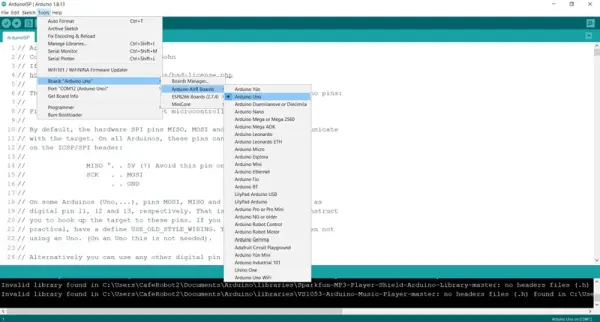
- We choose “Arduino as ISP” from the “Programmer” section of the same menu.

Now that the Arduino IDE is set up with the necessary libraries, we can move to loading example code and preparing a microcontroller.
To start, paste the supplied code snippet into a new Arduino sketch. This will serve as our testing program.
Next, we need to select the target microcontroller so its bootloader can be flashed. First, visit the provided Github link to determine which AVR category your microcontrollermodel falls under. For example, if using an Atmega8, it would be in the MiniCore group.
Once the microcontroller’s core group is identified, follow the steps in the “How to install” guide to incorporate support for that microcontroller model into the Arduino IDE. This will complete the environment setup needed before proceeding to flash the bootloader.
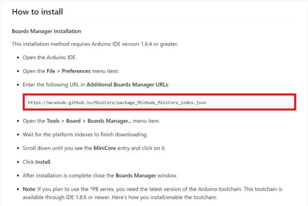
Begin by launching the Arduino IDE software. Navigate to the “Files” menu and select “Preferences” to open the configuration page. On this page, locate the “Additional Boards Manager URLs” option and paste the link copied previously.
Next, access the Board Manager by navigating to “Tools > Board”. This will initiate a download of additional board details.
Once the download completes, utilize the onboard search feature to look up “MiniCore”. Select this item and initiate installation to incorporate support for the target microcontroller board into the IDE environment. This finalizes the setup steps needed to flash the bootloader.
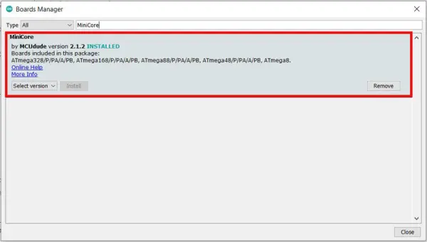
Navigate to “Tools > Board” and select the “MiniCore” item. Then, choose the target microcontroller of “Atmega8”.
Next, click “Burn Bootloader” located towards the end of the “Tools” menu. Allow the process to complete, which will be indicated by the message “Done Burning Bootloader”.
With the bootloader now installed on the microcontroller, it can be programmed using a USB-TTL converter and the Arduino IDE. Let’s test it out by uploading a simple code.
We can utilize the Arduino board as a USB-TTL interface by connecting its RX and TX pins to the microcontroller. Reconnect the Arduino to the computer after setting up the circuit.
Under “Tools”, select “Atmega8” for the “Board” and the corresponding serial port for the connected Arduino under “Port”.
To verify everything was done correctly, we will flash a basic “Blink” program to the Atmega8. Copy and paste the code provided below into a new sketch.
void setup() {
// initialize digital pin LED_BUILTIN as an output.
pinMode(8, OUTPUT);
}
// the loop function runs over and over again forever
void loop() {
digitalWrite(8, HIGH); // turn the LED on (HIGH is the voltage level)
delay(100); // wait for a second
digitalWrite(8, LOW); // turn the LED off by making the voltage LOW
delay(100); // wait for a second
- Can an Arduino be used as an ISP to flash AVR bootloaders?
Yes, Arduino boards can function as an In-System Programmer to flash bootloaders onto AVR microcontrollers using the ArduinoISP sketch. - What sketch must be loaded onto the Arduino to use it as an ISP?
The ArduinoISP sketch must be loaded onto the Arduino board to enable it to operate as an ISP. - Which Arduino pin is used to reset the target microcontroller in the ArduinoISP sketch?
Pin 10 is used to reset the target microcontroller. - How do you select the Arduino as the programmer in the Arduino IDE?
In the Arduino IDE, choose Arduino as ISP from the Programmer section of the Tools menu. - What additional software setup is required to support an Atmega8 target?
Install the Arduino IDE, add the Additional Boards Manager URL for the core, open Board Manager, search for MiniCore, install it, then select Atmega8 under Tools > Board. - How is the bootloader burning process started in the Arduino IDE?
After selecting the target board and programmer, click Burn Bootloader from the Tools menu. - How do you test the microcontroller after burning the bootloader?
Use the Arduino as a USB-TTL interface, select the correct board and serial port, then upload a simple Blink sketch to verify operation. - Which pins provide hardware SPI used by ArduinoISP?
The hardware SPI pins MISO, MOSI, and SCK on the ICSP/SPI header (or digital pins 12, 11, and 13 on many Arduinos) are used for programming the target.