Welcome to my Mario 64 Cake Carnival Timing Game! The cake is modeled after the end screen in Mario 64. The active light moves around the cake in a circle. The goal of the game is to stop the light on the star by pressing the button on the cake cutter. The game gets more difficult after each success by incrementing the level and speed. An LED matrix in the center of the cake is used to display the level. All of the electronics are inside the cake and cake stand. If you fall below zero you’ll get a sad face, but reach level 10 and get a bright smile!
Step 1: Supplies
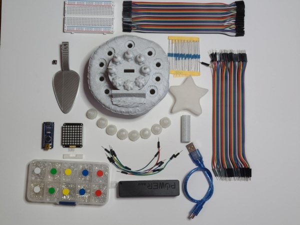
– USB power bank
– Arduino Nano power cable (needs to be small)
– Two 20 cm male to male wires
– 20 10 cm male to female wires
– Tape
– 3D printer
– White Filament (or another color you can paint over)
– Paint
– Arduino IDE
– Soldering equipment
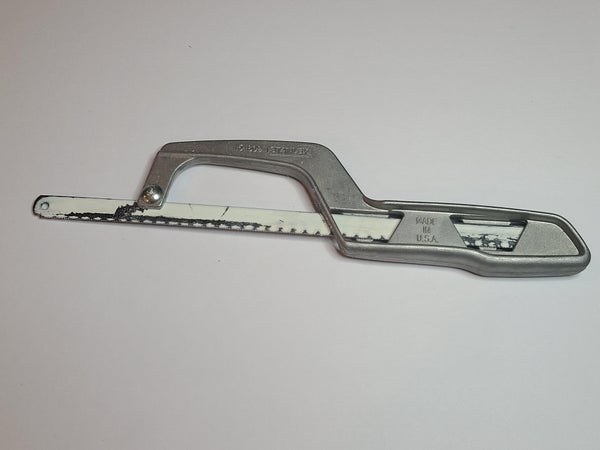
– Saw/other method of cutting a breadboard. (This can be substituted by printing a larger cake)
Note: I have not necessarily bought products specifically from these links. They appear similar.
Step 2: Print Parts
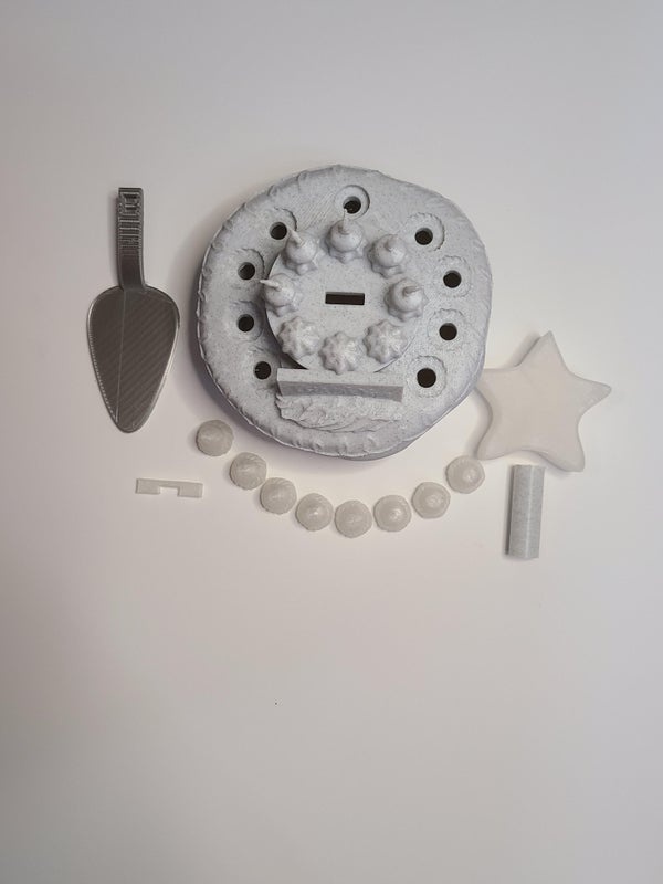
Print eight “CakeLEDStrawberries” in clear filament. You may need to adjust the scale slightly because of different printing tolerances.
Print the “cakeLEDstar” and “matrix balance bottom” in clear filament.
The “cake scoop” can be printed in silver or in white, then painted silver.
Print one of everything else in an easily paintable color (white is best).
Only the “CakeStarPipe” should be printed without supports.
Step 3: Paint Parts
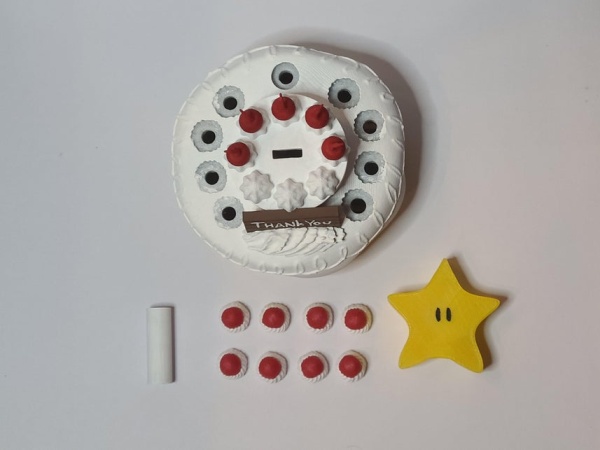
Painting the cake base simply requires following the depicted colors; yellow, white, brown, and dark brown. The sign should have dark and light brown stripes horizontally across it. For further reference, search “Mario 64 ending cake”.
The pole should be painted or printed white.
Painting the clear parts requires some testing. You’ll likely need 3+ layers of white on the strawberries’ whipped cream to block the light. The red will require judgement to see how many layers it takes to best let the light through. For me, it took two layers. If you don’t like the way details in the paint show up, you may also want to leave the strawberries clear. I found that the inaccuracies of paint layers when light shines through aren’t too problematic, since the lights are only on for a maximum of 2 seconds.
The star required one layer of yellow paint and then black for the eyes.
If you didn’t use silver filament on the cake cutter, paint it silver.
Step 4: Soldering
Straighten all four pins on the button. Solder two 20 cm male to male wires to the button. Then, thread the wires through the cake scooper so the button locks in. If necessary, add electric tape to prevent a short.
Step 5: Breadboard Reference
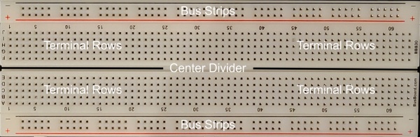
I will refer to the parts of the breadboard with these names.
Step 6: Cutting Breadboard
Using a saw, cut down the center divider of the half-size breadboard. Optionally, cut off the extruded bits on the breadboard with a dremel or saw. This step is necessary for the breadboard to fit easily in the cake.
Step 7: Electronics Button Setup
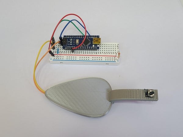
Place the Arduino Nano as seen in the image. It’s important to place it in the middle to leave space for the power cable on one side and the wires for the button on the other.
Use two 10 cm female to male connectors to wire Arduino pins D13 and 3v3 to separate, empty terminal rows. They must be on the opposite side of where the power cable is inserted.
Take the wires attached to the button and put one in the terminal row connected to the D13 pin and one in the terminal row connected to the 3v3 pin.
Place a 220 ohm resistor from the column which D13 is wired to into the nearest bus strip (the long connections on the edge of the breadboard).
Use a short cable to attach the GND pin to the nearest bus strip.
Place a 220 ohm resistor connecting the two bus strips. Normally, each LED should have it’s own resistor, but because only one LED is on at a time, one resistor is sufficient.
Step 8: Electronics Matrix Setup
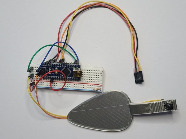
Attach 20 cm female to female connectors to the A4, A5, 5V, and GND pins. Tape the non-connected ends together so that the 5V pin is on the left, GND next to that, then A4 then A5. Mark or color code the wires in a way that will allow you to be able to attach them to the LED matrix.
Step 9: Electronics LED Setup
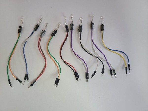
Take two 10 cm male to female wires and place an LED in the two female ends. Color code your wires or mark them so you’ll know which wire attaches to the positive end of the LED (the long pin). Tape the female ends together.
Repeat this nine times. Eight should have a red LED and one should have a yellow or orange LED.
Next, take one LED and wires set and place the positive end in D2 and the negative end in the further bus strip. Repeat this with D3, D4…D9, and D10. Make sure that the LED from D6 is the orange or yellow LED
Attach the LED matrix to the four taped female ends. 5v goes to vcc, GND to GND, A4 to SDA, and A5 to SCL.
Step 10: Code
 /*This a minigame where the active light moves circularly around a group of lights.
 * When the button is pressed the light stops and if the light stops in the middle the level increases also increasing the speed.
 * if the button is pressed one away from the middle the speed and level stays the same
 * if the button is pressed and it lands on a light which isn't the middle or next to the middle the level and speed is lowered.
 *
 * Digital ports 2-10 are each wired directly to the positive end of LEDs.
 * The other end of the LED is in ground.
 * The button has 5V in and a second wire in inputting to D13 and a resistor wired to ground
 *
 * The Matrix screen is wired:
 * 5v to vcc
 * GND to GND
 * A4 to SDA
 * A5 to SCL
 *
 * At a negative level a sad face is displayed and at levels >= 10 a happy face is displayed.
 */

//Matrix Libraries
#include <Wire.h>
#include <Adafruit_GFX.h>
#include "Adafruit_LEDBackpack.h"

Adafruit_8x8matrix matrix = Adafruit_8x8matrix();

static const uint8_t PROGMEM    // Setting Static Constants for the LED Matrix
  Sad_bmp[] =                    // Declaring sad face
  { B00000000,
    B01100110,
    B01100110,
    B00000000,
    B00111100,
    B01000010,
    B01000010,
    B00000000
 },
  Happy_bmp[] =     //declaring happy face
 {
  B00000000,
  B01100110,
  B01100110,
  B00000000,
  B01000010,
  B01000010,
  B00111100,
  B00000000
 };

const int buttonPin = 13;     //Where the button inputs
int LEDmin = 2;      //The port number which the first LED is hooked on
int LEDmax = 10;
int activeLED = 2;   //the light the sequence will start on
bool dirflag = true;      //flag used to determine the direction of the LED
int lightRate = 125;      //rate in ms for how long each light stays on
int level = 0;     //stores what level the player is on
boolean buttonUp = true;      //flage which ensures the button isn't being held
const int accelRate = 1.2;     //the rate the lights speed up as levels change
const int maxLevel = 10;     //the level at which a smile face will be displayed

void setup() {
  matrix.setTextSize(1);                          // Setting matrix text size to 1
  matrix.setTextWrap(true);                     // Preventing text wrapping to scroll text continuously through matrix
  matrix.setTextColor(LED_ON);                  // Turning LED On
  matrix.setRotation(1);                  // rotate
  matrix.begin(0x70);  // pass in the address
  matrix.setCursor(random(0,4),random(0,2));                   // Where the numbers should be printed, can't center so why not have them jump around!!!
  matrix.clear();
  matrix.print(level);            //start with 0 on screen
  matrix.writeDisplay();

  Serial.begin(9600);             //start Serial communication

  //Initialize LED pins
  pinMode(2, OUTPUT);
  pinMode(3, OUTPUT);
  pinMode(4, OUTPUT);
  pinMode(5, OUTPUT);
  pinMode(6, OUTPUT);
  pinMode(7, OUTPUT);
  pinMode(8, OUTPUT);
  pinMode(9, OUTPUT);
  pinMode(10, OUTPUT);

  //initialize pin attatched to button
  pinMode(buttonPin, INPUT);
}

void loop() {
  int buttonState = digitalRead(buttonPin);       //get the state of the input when button pressed == HIGH when not pressed == LOW

  if (buttonState == HIGH) {              //if the button is pressed
    if (buttonUp) {                 //ensure the button is not being held to repeat the loop
      if (activeLED == 11) {            //prevents a bug where no light turns on
        activeLED = 2;
      }
      digitalWrite(activeLED, HIGH);          //light up on the light where the button was pressed

      if (activeLED == 6) {             //if stopped on the middle light
        lightRate /= accelRate;       //speed up
        level++;                //increment level
        matrix.setCursor(random(0,4),random(0,2));                      //Setting the cursor to a random location so the number jumps around since it can't be centered
        matrix.clear();               //matrix must be clear before printing


        if (level<0) {
          matrix.drawBitmap(0, 0, Sad_bmp, 8, 8, LED_ON);      // Drawing the sad face when the level is negative
        }
        else if (level>9) {                             //draw a happy face if the level is 2 digits
          matrix.drawBitmap(0, 0, Happy_bmp, 8, 8, LED_ON);
        }
        else {
          matrix.print(level);            //display the current level
        }
        matrix.writeDisplay();
      }
      else if (activeLED != 5 & activeLED !=7) {               //if the stop is not on a green light (middle light was checked, making sure it's not the two lights next to that)
        lightRate *= accelRate;                       //slow down
        level --;                               //decrease the level
         matrix.setCursor(random(0,4),random(0,2));
         matrix.clear();
         if (level<0) {
          matrix.drawBitmap(0, 0, Sad_bmp, 8, 8, LED_ON);
        }
         else if (level>maxLevel-1) {
          matrix.drawBitmap(0, 0, Happy_bmp, 8, 8, LED_ON);
         }
        else {
          matrix.print(level);
        }
         matrix.writeDisplay();
      }
    }
      delay(2000);        //stay with the stopped light for 2 seconds
      buttonUp = false;         //set the flag to false so if the button is held the loop isn't repeated
    }

  else {                    //when the button is up
    buttonUp = true;            //reset the flag so the button can be pressed to stop again

    if (activeLED == LEDmax+1){            //if the last LED is lit
      dirflag = true;
    }
    else{
      dirflag = false;
    }
    if (dirflag) {         //Increment based on the direction the led is going
      activeLED = LEDmin;
    }
    digitalWrite(activeLED, HIGH);      //light on
    delay(lightRate);                         //wait for the proper speed
    digitalWrite(activeLED, LOW);           //light off
    activeLED++;


  }
}
Source: Mario 64 Cake Timing Light Game