Makeblock is an aluminum extrusion based construction system that provides an integrated solution for aspects of mechanics, electronics and software design. With Makeblock you can make professional robots, toy machines or even art-ware. It’s super easy-to-use and helps bring your creations to life. The only limit is your imagination.
 For more information, please visit Makeblock website listed below:
www.makeblock.cc
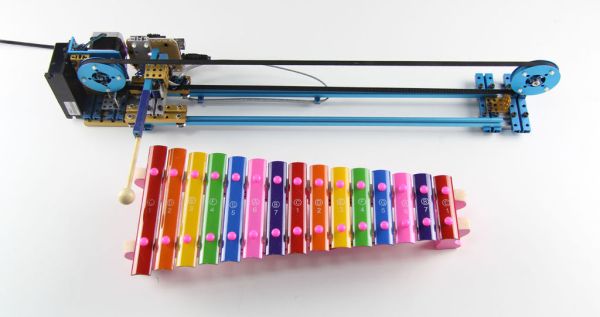
The Music Robot was built with the timing belt, sliding rail, step motor, electromagnet, motor driver and an Arduino Uno. And even you can build a play the piano robot with Makeblock by yourself.
So far the robot can be controlled by application via USB cable installed on computer, and it can also be controlled by the Smartphone through the Bluetooth. The special application for Android Phone is in planning.
Getting Started
This instructable, Making Music with Makeblock, will show you the step-by-step instructions on how to build a robot to play the Xylophone by Makeblock.
Now let’s have some fun!
Step 1: Materials list
Materials list:
1 × Beam 0808-144
3 × Beam 0824-64
7 × Beam 0824-80
4 × Beam 0824-96
1 × Beam 0824-128
4 × Bracket 3×3
1 × Bracket P3
1 × Step Motor Bracket
2 × Timing Pulley 90T
4 × Timing Pulley Slice 90T
1 × Link Rod
1 × Rubber band
2 × Slider 496
1 × Timing Belt
8 × Bearing for Slider
4 × Flange Bearing 4×8×3mm
1 × Shaft Connector 4mm
2 × Threaded Shaft 4×31mm
2 × Shaft Collar 4mm
2 × Headless Screw M3×5
2 × Copper Stud M4-15
12 × Plastic Rivet R4120
4 × Plastic Rivet R3075
2 × Countersunk Screw M3×8
14 × Screw M4×8
49 × Screw M4×14
8 × Screw M4×22
26 × Nut M4
Electronic Modules List:
1 × Arduino
1 × Acrylic Arduino Bracket
1 × Me – Motor Driver
1 × Limit Switch
1 × Step Motor
1 × Step Motor Controller
1 × Solenoid – 12v
1 × Wall Adapter Power Supply – 12VDC
Jumper Wires
Xylophone:
1 × Xylophone
1 × Xylophone Hammer
Step 2: Tools
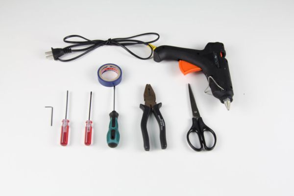
Tools
1.5mm Hexagonal Screwdriver
3mm Hexagonal Screwdriver
Cross Screwdriver
Slotted Screwdriver
Pincer Pliers
Scissors
Glue Gun
Adhesive Tape
Step 3: Driven Pulley Holder
Materials List:
3 × Beam 0824-80
2 × Beam 0824-96
1 × Bracket 3×3
1 × Timing Pulley 90T
2 × Timing Pulley Slice 90T
4 × Plastic Rivet R4120
2 × Flange Bearing 4×8×3mm
1 × Threaded Shaft 4×31mm
1 × Shaft Collar 4mm
1 × Headless Screw M3×5
2 × Screw M4×8
1 × Nut M4
10 × Screw M4×14
Procedure:
1. Install the Beam 0824-80 on Beam 0824-96 by using a Screw M4×14.
2. Install the other 3 Screw M4×14.
3. Install another Beam 0824-80 on Beam 0824-96 with 4 Screw M4×14.
4. Install the Beam 0824-80 on Beam 0824-96 to make a Driven Pulley Holder.
5. Install the Bracket 3×3 on Beam 0824-96 with 2 Screw M4×8.
6. Put a Timing Pulley Slice 90T on the Timing Pulley 90T.
7. Insert a Plastic Rivet R4120 into the holes on the Timing Pulley Slice 90T and the Timing Pulley 90T.
8. Insert the other 3 Plastic Rivet R4120.
9. Turn over the Timing Pulley Slice 90T and the Timing Pulley 90T.
10. Put the other Timing Pulley Slice 90T on the Timing Pulley 90T.
11. Press the Plastic Rivet R4120.
12. Insert the Threaded Shaft 4×31mm into the Flange Bearing 4×8×3mm.
13. Insert the Threaded Shaft 4×31mm with the Flange Bearing 4×8×3mm into the Timing Pulley 90T.
14. Insert the other Flange Bearing 4×8×3mm into the Timing Pulley 90T.
15. Put the Shaft Collar 4mm on the Threaded Shaft 4×31mm.
16. Insert a Headless Screw M3×5 into the Shaft Collar 4mm.
17. Install the Driven Pulley on the holder.
Step 4: Cut Link Rod
Materials list:
1 × Link Rod
Procedure:
Cut the Link Rod by using the Pincer Pliers.
Step 5: Slider Device and Music Play Arm
Materials List:
1 × Beam 0808-144
1 × Beam 0824-64
2 × Beam 0824-80
2 × Bracket 3×3
1 × Bracket P3
8 × Bearing for Slider
2 × Flange Bearing 4×8×3mm
1 × Threaded Shaft 4×31mm
1 × Shaft Collar 4mm
1 × Headless Screw M3×5
2 × Copper Stud M4-15
1 × Link Rod
5 × Screw M4×8
9 × Screw M4×14
8 × Screw M4×22
22 × Nut M4
1 × Solenoid – 12v
Procedure:
1. Insert the Screw M4×22 into the Bearing for Slider.
2. Insert the other 3 Screw M4×22 into the Bearing for Slider.
3. Insert and tighten Nut M4 per screw.
4. Insert the 4 Screw M4×22 with Bearing for Slider and Nut M4 into the Beam 0824-64.
5. Insert and tighten Nut M4 per screw on the Beam 0824-64.
6. Do the same as 1~5 discribe to install another Slider Device.
7. Insert 2 Screw M4×14 into the Beam 0824-64 to install it on the Slider Device.
8. Insert 2 Screw M4×14 into the Bracket 3×3 and the Beam 0824-64 to install them on the other Slider Device.
8. Insert 2 Screw M4×14 into the Bracket 3×3 and the Beam 0824-64 to install them on the other Slider Device.
9. Install 2 Copper Stud M4-15 on the Beam 0824-64 by 2 Screw M4×14.
10. Put the Solenoid – 12v on the Beam 0824-64 next to the Copper Stud M4-15.
11. Use the Link Rod and 2 Screw M4×14 to fix the Solenoid on the Beam 0824-64.
12. Insert the Flange Bearing 4×8×3mm into the Bracket P3.
13. Insert the Threaded Shaft 4×31mm into the other Flange Bearing 4×8×3mm.
14. Insert the Threaded Shaft 4×31mm with the Flange Bearing 4×8×3mm into the Bracket P3.
15. Put the Shaft Collar 4mm on the Threaded Shaft 4×31mm.
16. Insert a Headless Screw M3×5 into the Shaft Collar 4mm.
17. Tie the electromagnet core of the Solenoid – 12v to the Beam 0808-144 by Iron Wire.
18. Install the Rubber Band into the Bracket 3×3.
19. Install the Music Play Arm on the the Bracket 3×3.
20. Insert a Screw M4×14 into the Beam 0808-144 with a Nut M4.
21. Connect the Bracket 3×3 and the Beam 0808-144 by the Rubber Band.
22. Install the other Bracket 3×3 on the Bracket P3.
Step 6: Step motor and electronic modules Holder
Materials List:
2 × Beam 0824-64
2 × Beam 0824-80
2 × Beam 0824-96
1 × Beam 0824-128
1 × Bracket 3×3
2 × Screw M4×8
1 × Limit Switch
16 × Screw M4×14
Procedure:
1. Install the Beam 0824-64 on Beam 0824-96 by using a Screw M4×14.
2. Install the other 3 Screw M4×14.
3. Install another Beam 0824-64 on Beam 0824-96 with 4 Screw M4×14.
4. Install the Beam 0824-128 on Beam 0824-96 with 4 Screw M4×14.
5. Use the Glue Gun to install the Limit Switch on the Bracket 3×3.
6. Install the Bracket 3×3 with the Limit Switch on Beam 0824-64.
7. Install the Beam 0824-80 on Beam 0824-64 to make the Step Motor Holder.
8. Install another Beam 0824-80 on Beam 0824-128 to make the Electronic Modules Holder.
Step 7: Install to the Slider
Materials List:
2 × Slider 496
8 × Screw M4×14
Procedure:
1. Install the Slider Device to the Slider.
2. Install the Driven Pulley Holder to the Slider.
3. Install the Step Motor and Electronic Modules Holder to the Slider.
For more detail: Making Music with Makeblock

