Sneel is the name of my snake / eel swimming robot. This is documentation of hardware, software and mechanical design of Sneel_003.
urethane flex tubing, microcontrollers, Zigbee wireless radio, hose clamps, wires, servo motors, titanium servo brackets, silicon, marine grease, epoxy, pond pump
Sneel is a swimming robotic water-snake, constructed to explore lifelike, sinuous motion in an aquatic robot. It is designed to navigate unknown territory and extreme terrain.
Sneel is inspired by Protei, (protei.org), an international project for the design of a fleet of open source, robotic, unmanned sailboats. Sneel is a development of Protei_007.
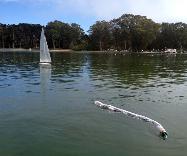
Sneel_003 swimming in San Francisco, California, Spreckles Lake, Golden Gate Park:
Sneel is an open-source, biomimetic, locomotive, aquatic robot. The electromechanical design of Sneel mimics the structure and motion of a real water snake, as a test to explore swimming behavior in an undulating linear robot. The inspiration for Sneel originates from a fascination with reptilian forms of motility and the implications of modelling hardware from biological structures and functions. Sneel uses a custom-written software library to propagate an oscillating wave down a line of servo motors that comprise the robot’s body. The current model is a platform for the development of other low-cost snake drones, with semi-autonomous navigational control for waypoint following, and sensing capabilities for obstacle avoidance. Worldwide applications for Sneel include remote marine data collection of salinity / toxicity levels, nuclear level monitoring, pipeline or underwater exploration, fishery monitoring, and oil-collection.
Sneel version 2 swimming like a real snake:
Step 1: Bill of Materials
5x Lynxmotion servo brackets
5x Lynxmotion C-brackets
5x injection molded servo hinge
urethane dust collection tube, 5′ x 2.5″
convoluted hose clamp
5/16″ tubing
5/16″ hose clamp
2x shop vac 2.5 to 1.25″ vacuum reducer
5x servo bracketshttp://www.seeedstudio.com/depot/bracket-for-rb421-servo-p-939.html?cPath=0
urethane sealant
marine grease
marine epoxy sealant
o rings
carbon fiber 3x (1/32″, 1″x12″ strips)
rubber about 1/8″ thick, 2″x10″ at least, like this neoprene works well
loctite (green)
nylon string as a tether
optional:
inner tube or valve for positive pressurizing with a bike pump
silica gel packs
10 Servo motors (I recommend these Hitec ones with Karbonite gears but these are a bit pricy. Whatever you get, the nylon gears will ear out quickly so I warn against them)
3 6V NiMh battery packs
Arduino UNO
1 seeeduino mega
Xbee explorer
2x xbee series 1
xbee wireless shield
servo motor shield
servo extension wire
xbee breakout + 2 rows of 10 male header pins + 2 rows of xbee 2mm female headerssupplies:
wires
needlenose pliers
angle snips
wire strippers
small screwdriver
4-40 screws, lock or toothed nuts, and bolts
2-56 screws, lock or toothed nuts, and bolts
solder iron + solder
hack saw
drill or drill press
3 mm drill bit
optional:
dremel
Step 2: Waterproof the servo motors
-apply silicon marine sealant around the two seams in the plastic of the servos, around the spot where the wires are inserted, and where the screws are mounted on the bottom.
-Let the motors dry for 24 hours…-Unscrew the servo horn (the round plastic top of the servo motor).
-Apply petroleum or marine grease around the toothed shaft, and slip an o-ring around the shaft.
-Put back on the round servo horn. Make sure it is centered (turn it one direction and make sure that it rotates about 90 degrees from center one direction and 90 degrees the other direction).
-Screw back on the circular plastic servo horn.
Step 3: Prepare the frame: cut the carbon fiber
With a hacksaw, cut the carbon fiber into 4 inch pieces (each 12″ x1″ strip should be cut in 3 parts). I used a dremel to round the jaggedy corners.
-Lay out one of each servo bracket 3 inches apart. Mark on the carbon fiber where the two large holes in the brackets line up, so you can drill here to screw them into the carbon fiber.
-Drill the 4 holes in each piece of the carbon fiber using a 3 mm drill bit, or around that size.
-Do this with 7x 4″ pieces.
Step 4: Prepare the frame: attach the brackets to the carbon fiber
Using the fat screws that came with both brackets, line up the holes you cut with the holes in the brackets.
-Screw in the screws to attach the carbon to the brackets. Make sure you screw with the bolt on the backside of the brackets as shown in the photo.
Step 5: Prepare the frame: attach the c-brackets
-Line up the rubber with the c-bracket middle section (see image) and cut 5 pieces. They will be about 1″ x 2″-Line up the cut piece of rubber with one of the c-brackets, and draw a dot on the rubber where two of the holes line up.
-Use a pin to poke a hole in the rubber at the two hole-marks.
-Insert the 2-56 screws from the black clamp, through the rubber (pop it or screw it through), then through the red bracket.
-Do this for every black/red bracket pair.
NOTE: from the image, I did things in a slightly different order than described above – you can see my servo is already attached to the servo bracket. This made it significantly more difficult to screw in the two screws here. Also, I ended up getting 1/2 inch screws but at first I was using 1 inch screws and had to grind or cut off the excess.
Step 6: Prepare the frame: Mount the servos on the brackets
In the package with the servos, there are a few parts. Grab the small rectangle cube.
-Insert this into all four of the holes on the servo motor. Note that the rubber has a flat side. This side should be facing outwards.
-on 5 of the servos, adhere the injection molded joint (unless you have c-brackets with bearings in the bottom)
-Place the servo in the bracket as shown – the servos with the injected molded joint go on the black servo bracket.
-Screw in the 4×40 screws. Place a lock nut on the bottom and screw in the bolt.
Step 7: Prepare the frame: Mount the c-bracket pairs to the servo brackets
Mount the red servo-brackets to the red c-brackets, and the black to the black:
RED:
Slip the c bracket over the servo horn and under the servo bracket, as shown in the photo. Use the screw and bearing to secure it in place.
BLACK:
Slip the c bracket over the servo covering most of its body. Slip it over the servo horn and under the servo bracket. Make sure that the top side on the servo horn is the side with one large hole and four small holes. The injected molded segment on the bottom should pop into place in the small hole.
Now you should have a full length snake like structure.
Step 8: Screw in the servo horn to the bracket
line the holes up with the brackets and the servo horn.
-Make sure that your horn is centered (you can spin it in one direction and the other direction, then bring it about halfway back turned, to the center position, so if you put your bracket on aligned straight with the servo it will be calibrated to center position.
-use a small screwdriver to screw the bracket and the round plastic servo horn together. I like to pinch them together with pliers to make sure holes line up.
The brackets and servos should rotate freely. You should apply some grease between the two metal brackets if there is friction.
You can also apply loctite to some of the screws so that they dont come out. Make sure not to do this before you are certain you are finished, because it is very hard to undo the screw once you’ve applied loctite. Also, the green loctite is a little less permanent.
At this point, your snake body is ready!
Step 9: Make the circuit
Prepare the xbee breakout board (solder on the 2 rows of male headers and 2 rows of 2mm xbee female headers)
-Insert the xbee onto it.
-I’m using a servo motor shield from seeed studios, but I am sort of just using it as a perf board, but a convenient one because all the ground and power pins to my servo motor are already jumped together, with a screw terminal for the battery input. And ignore those wires hanging off the board – I had previously soldered on female header pins for another use of the board, so I removed them so I could use this here. I eventually clipped them off but you can see them in the pics.
-So if you have the servo shield, solder on the screw terminal; two rows of headers where the 6V and GND from the battery are connected. Solder on male headers so it will mount in your seeeduino (or Arduino) mega. I’m using the seeeduino again because i had it around, and because it is smaller so it fits better into the skin tube (the protective outer layer).
Note: an Arduino mega is necessary not because of the numbers of outputs but because the flash memory space in the Arduino UNO is not large enough.
-jump xbee pin 1 (3.3Vin) to Arduino 3.3V pin (see red wire)
-jump xbee tx (pin 2) to Arduino RX (pin1) (see yellow wire)
-jump xbee ground (pin 10) to Arduino gnd (see black wire)
-jump power from the 6V battery input to the Arduino VIN pin (green wire)
-Solder on wires from all the digital output pins (as many servos as you are using).
-place on the servo connectors (Red, black, white here) and insert the dOUT wires from Arduino into the servo cables (white signal wire).
NOTE: if Arduino is to be housed in the frotnt of the snake, connect the pins low to high from Arduino to the servos that are most close to the head to far away) . in other words: the first servo (as in when the snake is moving ahead, the servo at the HEAD) should be digital pin 2, and the tail end servo should be digital pin 11.
-Screw in wires to the screw terminals to attach to 6V and GROUND from your batteries.
-I clipped the extra metal off (you shouldn’t have to do this if you are starting from a clean board, not one with female header pins soldered in)
Step 10: Upload the firmware
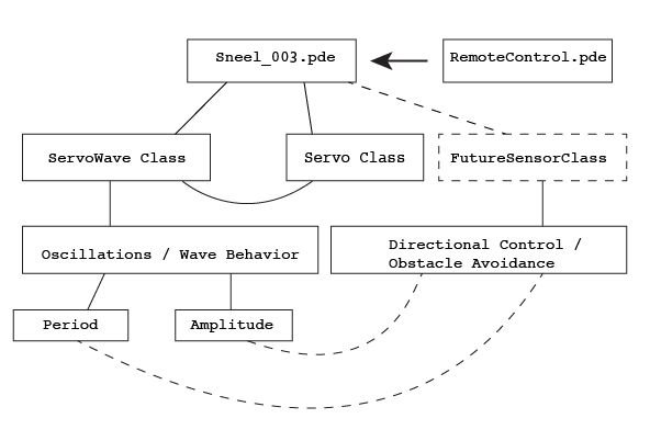
I wrote a software library to easily generate wave locomotion based on oscillation. It calls on the Servo Arduino library to generate a sine wave propagating down the line of servos. It allows for modularity to change the sensory input, wave parameters, and number of servos. Download the code here. Upload it to Arduino, without the xbee plugged in (when the xbee is plugged in, the tx and rx pins (pins 1 and 0) on Arduino mega are used references a class that propagates a sine wave down a line of motors.
During each loop cycle:
-The main program, references a class that propagates a sine wave down a line of motors.
-listens to a wireless RC protocol communicating to the snake via the joystick
/Code written by Gabriella Levine to take inputs from button pins and output
//chars to the serial port
// set pin numbers:
const int buttonPin1 = 2; // the number of the pushbutton pin
const int buttonPin2 = 3; // the number of the pushbutton pin
const int buttonPin3 = 4; // the number of the pushbutton pin
const int buttonPin4 = 5; // the number of the pushbutton pin
const int buttonPin5 = 6; // the number of the pushbutton pin
const int buttonPin6 = 7; // the number of the pushbutton pin
const int ledPin = 13; // the number of the LED pin
// variables
int buttonState1 = 0; // variable for reading the pushbutton status
int buttonState3 = 0; // variable for reading the pushbutton status
int buttonState2 = 0; // variable for reading the pushbutton status
int buttonState4 = 0; // variable for reading the pushbutton status
int buttonState5 = 0; // variable for reading the pushbutton status
int buttonState6 = 0; // variable for reading the pushbutton status
 void setup() {
Serial.begin(9600);
// initialize the LED pin as an output:
pinMode(ledPin, OUTPUT);
// initialize the pushbutton pin as an input:
pinMode(buttonPin1, INPUT);
pinMode(buttonPin2, INPUT);
pinMode(buttonPin3, INPUT);
pinMode(buttonPin4, INPUT);
pinMode(buttonPin5, INPUT);
pinMode(buttonPin6, INPUT);}
void loop(){
if(Serial.available()>0){
byte incomingByte = Serial.read();
if(incomingByte==’1’||incomingByte==’2’||incomingByte==’6’||incomingByte==’5’||incomingByte==’0′)
{
digitalWrite(ledPin, HIGH);
delay(10);
digitalWrite(ledPin, LOW);}}
// read the state of the pushbutton value:
buttonState1 = digitalRead(buttonPin1);
buttonState2 = digitalRead(buttonPin2);
buttonState3 = digitalRead(buttonPin3);
buttonState4 = digitalRead(buttonPin4);
buttonState5 = digitalRead(buttonPin5);
buttonState6 = digitalRead(buttonPin6);
// check if the pushbutton is pressed.
if (buttonState1 == HIGH) {
Serial.print(‘1’);
}
if (buttonState2 == HIGH) {
Serial.print(‘2’);
}
if (buttonState4 == HIGH) {
Serial.print(‘4’);
}
if (buttonState3 == HIGH) {
Serial.print(‘3’);
}
if (buttonState5 == HIGH) {
Serial.print(‘5’);}
if (buttonState6 == HIGH) {
Serial.print(‘6’);}
delay(10);}
For more detail: Make a swimming Robo-Snake Using Arduino