Summary of Make a Desktop Tamagotchi Using Arduino
This article describes the design and construction of a desktop Tamagotchi using an Arduino-based system and a 16x16 LED matrix display. The project involves building hardware with an ATmega328P microcontroller, LED matrices controlled by shift registers and transistor arrays for multiplexing, and peripherals like buttons and a buzzer. The construction emphasizes a two-board design: one for the LED display and one for the electronics, allowing a clean visual appearance with the electronics hidden behind the display. Proper resistor calculations and soldering techniques are also detailed.
Parts used in the Desktop Tamagotchi:
- ATmega328P with Arduino bootloader
- 16Mhz crystal
- Two 22pF capacitors
- Programming device (Arduino platform or FTDI adapter)
- 4 x 74HC595 shift registers
- 2 x ULN2803 Darlington transistor arrays
- DS1302 RTC module
- 32.768kHz crystal
- 3V coin cell battery holder and battery
- 4 x right angled push buttons
- Piezo buzzer
- 4 x 8x8 LED matrix modules
- 16 x 330 Ohm resistors
- 2 x rows of 16 female pin headers
- 2 x rows of 16 male pin headers
- 1 x row of 4 female headers (for programming)
- 5 x 100nF capacitors
- 1 x 10uF capacitor
- 1 x 10K resistor
- Power jack connector
- 5V DC wall wart power supply
- Proto board (large piece)
- Wires for connections
- Soldering iron and solder wire
- Cutters and needle nose pliers
- Optional: solder braid or solder pump
One day I was sitting behind my desk at work and I got that weird need to build something, after looking around for a bit I got my eye on an LED matrix and that sparked an idea in my head : “I WANNA MAKE A TAMAGOTCHI”.
So for those of you that don’t know what the heck is a Tamagotchi here is a little snip-it from Wikipedia :
“The Tamagotchi (たまごっち Tamagocchi?) is a handheld digital pet, created in Japan by Akihiro Yokoi of WiZ and Aki Maita of Bandai. It was first sold by Bandai in 1996 in Japan.”
So my take on this classic toy is to make it in to a desktop gadget with an LED matrix for a display, and an Arduino for brains to make it more accessible to people. With that said join me as we design, build and program the World’s first (As far as I know) desktop Tamagotchi.
Step 1: Getting The Right Stuff
So like any other electronics project you will need to get some basic tools:
1) Soldering Iron
2) Some solder wire
3) A pair of cutters
4) A pair of needle nose pliers
Optional : Get some solder braid or a solder pump to fix soldering mistakes
As for the electronics the parts list a bit longer, here is what you will need to get:
1) An ATmega328P with the Arduino bootloader + 16Mhz crystal with two 22pF caps
* You will need something to program the chip as well like an Arduino platform or an FDTI adapter
2) 4 x 74HC595 shift registers
3) 2 x ULN2803 Darlington transistor array
4) 1 x DS1302 RTC + 32.768kHz Crystal
5) 1 x 3V coin cell battery holder + the battery.
6) 4 x right angled push buttons
7) 1 x Peizzo Buzzer
8) 4 x 8×8 LED matrix modules
9) 16 x 330Ohm resistors (you will need to calculate the value for your matrix)
10) 2 x row of 16 female pin headers
11) 2 x row of 16 male pin headers
12) 1 x row of 4 female headers(For programming)
13) 5 x 100nF cap
14) 1 x 10uF cap
15) 1 x 10K resistor
15) Power jack connector
16) 5V DC wall wart
17) A big piece of protoboard
18) Some wires for connections
Step 2: The Hardware Side
Even if this project if mostly software focused we will need to build the hardware first to make life writing code and debugging it easier.
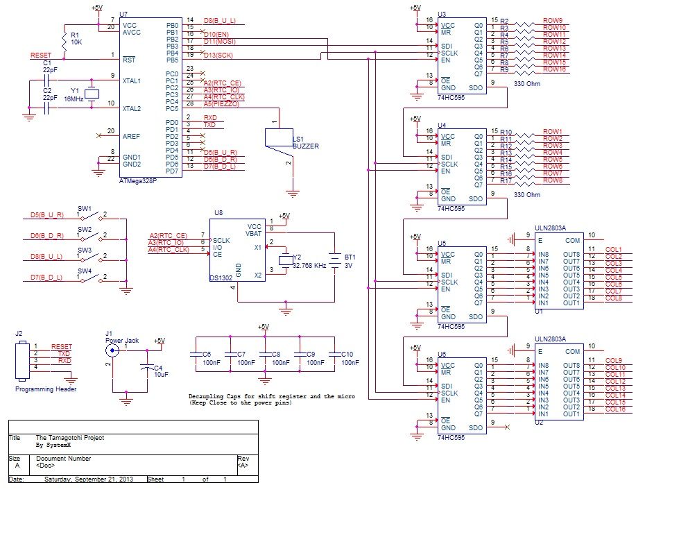
The hardware consists of 2 main parts: The microcontroller part and the LED display.
The microcontroller part is very straight forward, it’s an standalone Arduino(ATmega328 with the Arduino bootloader) with
some peripherals(4 buttons, a buzzer and an RTC), but the it’s the most critical part as it does all of the thinking.
The LED display part is a bit more complex and takes some time to solder up. This circuit consists of 4 shift registers (74HC595),
2 darlington transistors arrays (ULN2803) and 4 8×8 LED matrices.
Like most LED displays it comes as no surprise that the display need to be multiplexed(look it up it’s a pretty cool concept) because driving 16×16 LEDs individually will take 256 pins from the microcontroller and that’s just silly.
Even with the multiplexing approach we will still need 32(16 rows + 16 columns) pins from the microcontroller to drive the display which again we don’t have, so the solution is to use shift registers as an I/O expansion , 4 8 bit shift registers give us 32 outputs and it only takes 3 lines to control them all.
But the problems don’t end here because the shift registers can’t handle sinking the current of 16 LEDs (if a full row is lit) on one pin so we need to give it a hand with the help of the darlington transistor array that will act like a buffer that can handle big currents which can fry the shift registers.
So to recap we use 4 daisy chained shift registers to control the display, the first 2 drive the rows and the other 2 drive the columns with the help of the darlington array.
The only thing that needs to be calculated in this project is the value of the resistors that will drive the LED rows.
The formula is very simple and goes like so :
R = (Vsource – Vled)/ Iled
Vsource is 5V, Vled is the forward voltage on a single LED in the matrix and Iled is the forward current of that same LED.
You can also use online calculators to help you with this.
Step 3: The Construction Concept – LED board
When I started the build I wanted to get a clean look without using a case (finding the right case is a nightmare) so I went for
a two piece construction i.e. one board that holds the LED matrix and the second one with all of the electronics.
This way the only thing you see when you’re looking at the front is the LED display itself and all of the other stuff is hidden behind the display.
The first board with the LED matrix will dictate the size of the second one because you want to hide the other board behind the display. So place the matrix assembly on the board, mark where to cut and cut the board. Cut the second board so it will be the same size as the first one. The trick with this building style is to have to proto-boards of the same size, so it’s a good idea to sand the boards to get them to the same size.
Because I had 4 8×8 LED matrices I had to connect them together to get one 16×16 LED matrix, that’s quite simple and take just a bit of time to connect them together. The way you do it is by connecting the rows of the horizontal matrices with on and other and connecting the columns of the vertical matrices (I made the connections with some thin wire-wrapping wires).
Now the only part that is left with this board is connecting the headers that will connect the to boards together, the placement of this connector is decided by the position of the switches on the second board. The switches will be on the sides of the board so you can’t put the connectors on the edge of the board that’s why the connectors are placed about 4 holes from the edge.
There are two connectors one for the rows and the other for the columns.
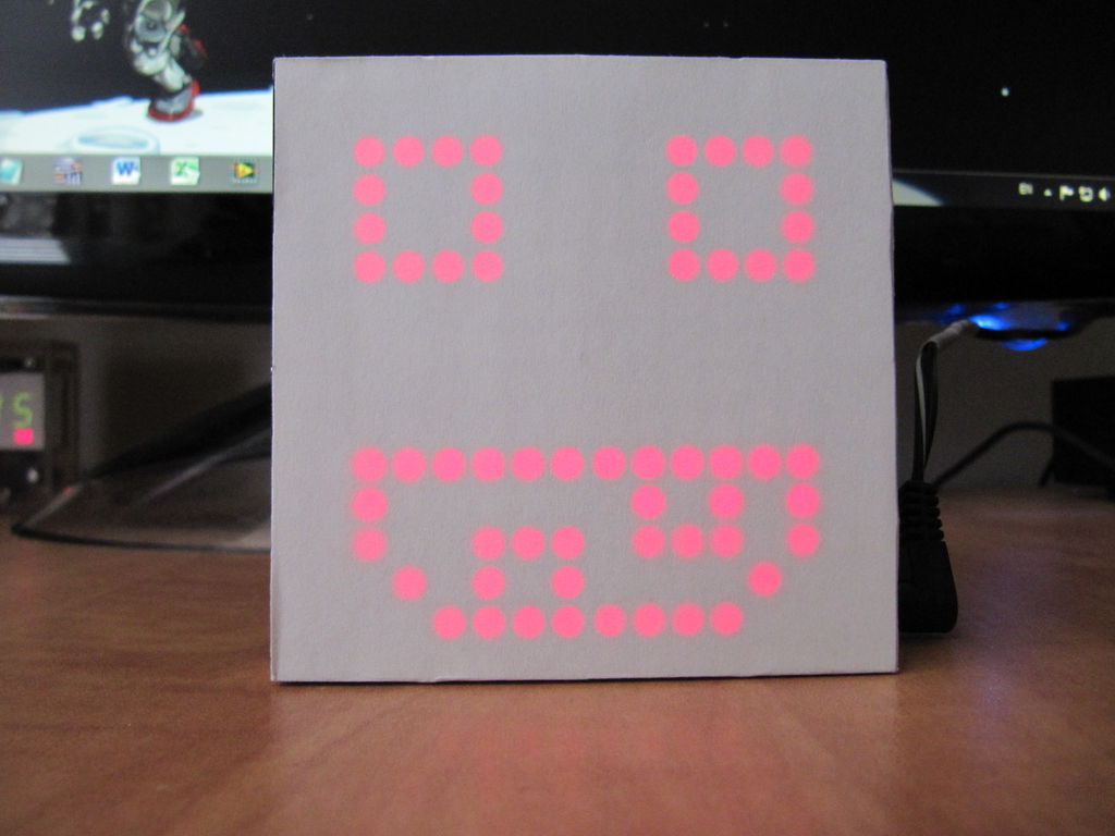
And to finish the look I recommend putting a sheet of white paper over the matrix to hide the assembly and get a clean look.
I glued the paper to the edges of the matrix so the display is safe from the glue.
For more detail: Make a Desktop Tamagotchi